|
|
Devices << ArduinoDevice | Software Overview | Sitemap | Downloads | Developers | Forums |
|
|
ArduinosArduinos are a great way to connect a wide variety of devices to Virtual wiring. If you are unfamiliar with Arduinos, you should read this entire section. If you only need to learn how to use Arduinos in Virtual Wiring systems, you may want to skip the "Overview" and "Making Connections" sections and read the rest.
OverviewAdding an Arduino to a Virtual Wiring System makes it possible to add thousands of other devices. Arduinos are microcontroller boards with lots of input/output (I/O) pins, standardized interfaces, and common programming libraries. Arduinos support a large number of hardware peripherals - lights, relays, motors, servos, pressure, humidity, temperature and light sensors to name a few. The two most popular and general purpose Arduinos at this time are the Uno and Mega. The Uno has 6 analog inputs (A0-A5), and 14 general purpose digital I/O pins (0-13). The Mega has 16 analog inputs and 54 general purpose digital I/O pins. In addition, both support a number of special purpose functions (SPI, I2C, Serial, and PWM pins as examples). 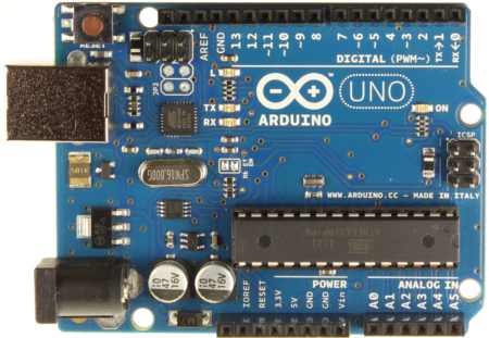
Making ConnectionsArduino boards have a set of sockets for connecting to other devices. In the photo above, you can see the black sockets on the top and bottom of the board. Each socket connects to an Arduino microcontroller I/O pin, and each I/O supports a number of different modes. Some pins can be analog inputs, digital inputs, and digital outputs. Others can be digital inputs, digital outputs, pulse width modulated (PWM) outputs, and servo outputs. A smaller number of others can be UARTs, SPI interfaces, and I2C interfaces. If you want to connect a simple device to an Arduino, you may be able to wire it directly to your Arduino sockets. For more complex devices, you can insert jumper wires into the Arduino sockets and run them over to a breadboard. Using breadboards, one can build fairly complex systems (though they may be fragile and lack a professional look). For more complex applications or for a more professional look, you can plug Arduino daughter cards into the Arduino sockets (Arduino daughter cards are called "shields"). Shields are stackable, so one Arduino can support more than one shield. The I2C InterfaceThe Arduino supports an I2C interface. I2C is a standardized interface useful for connecting peripherals to microcontrollers. It is a master-slave bus, so one I2C interface can be shared between the Arduino (the master) and many slave devices. Examples of I2C devices are complex sensors and motor controllers. The I2C interface consists of 2 pins, a clock and a bidirectional data pin. By default, Arduino's I2C interfaces power up disabled, and the I2C pins have another function. On Arduino Unos, the I2C pins default to being analog inputs A4 and A5. ShieldsFor more professional looking and robust applications, there are a bunch of small boards which plug into an Arduino's I/O connectors called shields. Shields are standardized boards which pick and choose the Arduino signals they need and then connect them to specialized circuits on the shield. Some examples of shields are breadboards, breakout boards, motor controllers, relay boards, precision ohm meters, Ethernet, and wireless networking boards. There are 100s of different shields available. The Grove SystemOne of the easiest and cheapest ways to connect devices to Arduinos we have found is using the GROVE system made by Seeed Studio. It doesn't support every device you might need, but it supports a lot. Seeed makes a Grove Base Shield that plugs neatly into an Arduino's connectors and brings its I/O pins to a well laid out set of 4 pin Grove connectors. The board is well labelled, so it's easy to see which Arduino pins are connected to which Grove connectors. Seeed Studio also sources a large number of devices for connecting to the connectors: LEDs, temperature sensors, light sensors, touch sensors, relays, servos, switches, joy sticks, buzzers, pressure sensors, gas sensors, to name a few. One can connect devices to an Arduino by just plugging things in. 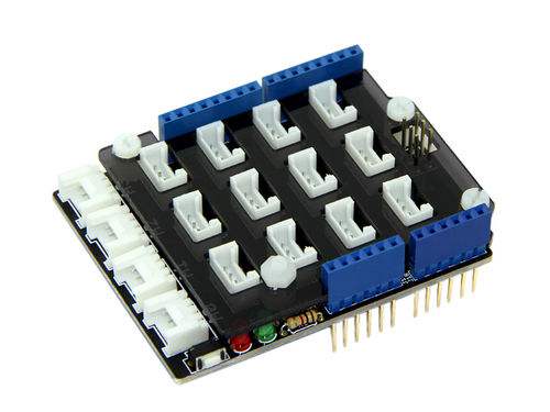
A good way to get started is to buy an Arduino Uno and a "Customize Your Grove Kit" from Seeed. A Grove kit includes a Base Shield, wiring harnesses, and your choice of ~10 Grove devices. An Uno from Amazon and a kit from Seeed can be had for less than $70. Uno's sell for less than $30. The Uno connects to the Virtual Wiring host system using a standard USB cable. 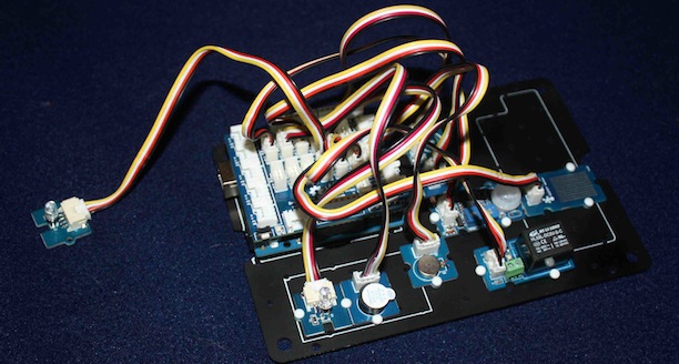
A compact and inexpensive standalone system can be built using a Raspberry Pi (which runs the Virtual Wiring system), an "A La Mode" board (which provides the Arduino Uno functionality), and a Grove Base shield. The total system cost is less than $100 (Grove devices not included). It makes a tidy little brick. 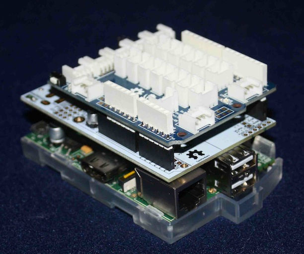
The A La Mode based system should probably be avoided for first time projects as our installation required configuration, programming the A La Mode with Firmata, and soldering connectors into the A La Mode board (for holding the Base Shield). An equivalent Raspberry Pi with a USB cable to an Uno and Base Shield is easier to build. ProgrammingSince Arduinos have microcontrollers, they have to be programmed. The Virtual Wiring system requires all Arduinos to be programmed with a common program called Firmata. Firmata (see www.firmata.org) is a program providing an interface for controlling an Arduino's I/Os. It lets another host computer define the mode of an I/O and what to do with it - set it, clear it, read it, etc. What's nice about the Firmata program is, once an Arduino is running the Firmata program, it probably won't need to be programmed again. You program your Arduino once, right after you buy it, and it just works thereafter. Most Arduinos come with Firmata pre-installed. We support Arduinos running Firmata software at version 2.2 or higher (2.3 or higher if you are using an Arduino's I2C bus). If, for some reason, your Arduino does not come pre-programmed with the proper Firmata, you can download the Arduino development software and program the Arduino yourself. The development software includes the Firmata application. See our How To Install Firmata page for more background and a step by step installation. Using Your Arduino in a Virtual Wiring SystemInstallationOnce your Arduino has the Firmata program installed, it is ready to be installed into a Virtual Wiring system. You install an Arduino by running a special "Arduino" Script. The Script creates an Arduino Device which represents your Arduino. Next, you can run Scripts upon the Ardunio Device, and these define which I/Os are in use, their modes, and Device terminals for accessing them. To install an Arduino into a Virtual Wiring system, you need to connect the Arduino's USB port to computer running Virtual Wiring. Next, you run the "Arduino" Script to get your Arduino Device. Click on the following link to learn how to run the Arduino installation Script. Pin ConfigurationAfter you have installed an Arduino and created your Arduino Device, you can run Arduino Device Scripts that define how your Arduino pins will operate. A Script defines the mode of an I/O (whether it's an input/output, etc.), and it defines a Device terminal for that I/O. The terminal gives you (and Virtual Wiring) an interface for controlling and/or monitoring that I/O. As an example, a Script could define a digital input with terminal name "input" on your Arduino Device. If you looked at your Arduino Device in your system, you'd see terminal called "input". If you looked at the the value of the "input" terminal, it would reflect the state (on or off) of the digital input pin. Most of the pins on an Arduino are configurable as inputs or outputs. Inputs can either be analog or digital, and outputs can be digital, pulse width modulated (PWM), or servo. In general, digital inputs monitor devices with an "on" or "off" state (switches are an example). Analog inputs monitor devices that output a range of values (a light intensity sensor, as an example). Digital outputs control devices with an "on" or "off" state (e.g. a relay or an LED). PWM outputs provide a digitized approximation of an analog output - an LED connected to a PWM output can be brightened or dimmed by controlling the duty cycle of the PWM. Servo outputs control the position of a servo. How Arduino pins are configured will depend on the physical devices that are connected to them, and to which pins the devices are connected. Most devices require only general purpose pin configurations. Click on the following link to learn how to configure Arduino pins. Installing Arduino Device DevicesIf there's a device which you can't connect to an Arduino using standard pin configurations, we may still support it. For example, there are I2C devices, which have their own set of I2C registers and sequencing requirements. In addition, there are shields with complex relationships between their various I/Os. For these more complex devices, we have a number of Arduino Devices Scripts. To learn more about these devices and their Scripts, visit to our Devices on Arduinos section. |
Catalina Computing, LLC.Copyright © Catalina Computing, LLC. (2013-2018) 
|
Page last updated: Tue May 15 17:19:27 2018 (UTC) |