|
|
Projects << StoreMonitoringProject | Software Overview | Sitemap | Downloads | Developers | Forums |
|
|
Frozen Food Store Monitor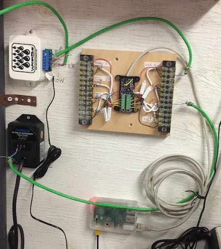
IntroductionA successful frozen food store was doing all the right things. A great product, excellent location, friendly staff. Everything was going great guns, and the owner, being proactive, was thinking, "How can I keep on eye on things when everyone's away?" The town power was reliable, and the weather had never been too severe. Still, there were rare power losses. Also, back when the store was just getting started, the building owner warned the store owner about possible flooding in the basement. It didn't happen often, but if it did, it could flood all the basement freezers. And there was always the possibility of a freezer door being left open overnight, or a freezer malfunctioning. So the store owner needed a way to sense basement water, a power failure, and freezer temperatures; in addition, supporting possible enhancements such as motion detection (in case someone broke into the store) was also desirable. Ideally, the system should be inexpensive as well, with no monthly charges. We built a complete system for less than $300. Store Monitoring RequirementsInitially, we made a list of requirements. They were:
Store LayoutThe store had a main floor and a basement. The main floor had some smaller freezers, and the basement had the biggest freezers. The main floor was finished, and the basement was unfinished. The basement also had the furnace as well as food processing equipment. Wired and wireless internet (WiFi) connections were available in the basement, and WiFi was available on the first floor. Given that there were going to be sensors in the freezer units and a water sensor in the basement, it was clear they would be spread throughout the store. Wired vs Wireless SensorsOne of our first decisions was what kind of sensor we should use - wired or wireless. Here are some the trade offs between the two.
The store had lots of equipment (freezers, heating systems, food processing equipment), so there was a good chance a wireless system would have dead zones, due to shielding from all the equipment. In addition, the basement was unfinished, so it would be easy to run small twisted pair wiring to all the sensors. Based on the store's configuration, we decided wired sensors were our best option. Wired sensors would work everywhere in the store, and given most of our wiring could be run easily in the basement, installation wasn't going to be much of a problem. Lastly, we saved a bit of money by choosing wired sensors. Component SelectionNext we chose the actual components for our system. We chose low power, reliable parts, which all were inexpensive as well. Host systemTo operate our store monitor, we needed a host computer. The host computer runs the Virtual Wiring software and connects to the sensors. Since Virtual Wiring runs on most any *nix computer, we chose a Raspberry Pi B+ computer. Raspberry Pis are inexpensive (we bought our Pi, flash memory, and case for about $50) and robust. Raspberry Pi power supply and USB cableTo power our Raspberry Pi, we chose an Apple iPad power supply and a short, 20 gauge USB power cable. This was not the cheapest option (the two cost about $25), but we've learned that there are lots of poor quality USB power supplies and skimpy USB power cables. We've been using Apple supplies, because they are solid and reliable, and they are easy to find. It's no fun finding out the hard way that you've made a poor power supply choice. Also, when you buy a USB power cable, make sure the power wires are 24 gauge or better, and keep the cable short. Long skimpy cables may not supply the voltage your Raspberry Pi needs. Water sensor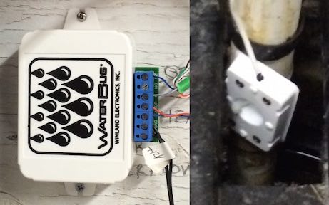
We chose a Windland WaterBug WB-200 water sensor ($60). These sensors are popular and have been around a long time. They are also guaranteed to work over stretches of 100 feet of wiring (or more), and you can connect up to 6 sensor modules to each base unit. WaterBug power supplyWe bought a 12V DC 500mA power supply ($8). The WaterBug will run on any 12V DC supply which supplies greater than 35mA. Our supply was designed to power a video system. We found it on Amazon. I/O Connections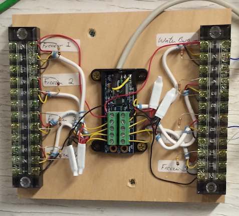
To do all the I/O for the system, we selected a DLP Designs DLP-IO8-G. We chose it because it was relatively inexpensive and it provides connectivity to basic on/off type sensors as well as to temperature sensors. It also supports analog sensors and has inputs for up to 8 separate sensors. To make it easier to connect to our I/O devices, we mounted the IO8 with 2 12-terminal terminal blocks (found on ebay). Because we had 8 possible sensors, all of which required a ground terminal, and some (the temperature sensors) which required power, we provided each of the 8 possible inputs with a ground and power connection as well (for total of 24 terminals). All our on/off devices and our temperature sensors required a small pull up resistor from the sensor input to the power terminal (+5V). We added the pull up resistors to the terminal blocks as well. Temperature SensorsThe DLP-IO8 supports DS18B20 type temperature sensors. These are easy to find on the Internet. We found a version on Adafruit.com which comes in a stainless steal case which is small and sturdy. These sensors require +5V, Ground, and a data line (with a pull up resistor). Depending on the distance of the sensor to the DLP-IO8, the pull up might vary. We sized our pull ups for 100 feet and found 499 Ohm pull ups were a good choice being both reliable as well as accommodating a wide range of wire lengths. Power Sensor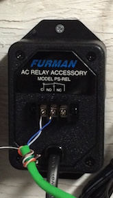
We wanted our system to sense when the power in the store went off. To sense power loss, we plugged in a Furman Power relay (which we bought on Amazon). When the relay looses power, two of its terminals open. We connected 2 wires from the relay to a ground and a sense input on a DLP-IO8 terminal block. When power was lost, the relay would open. Once the circuit was open, the pull up on the terminal block would pull the sense input to +5V, and signal to our Raspberry Pi a loss of power. UPSTo allow the system to work after power loss, we used a standard UPS. We plugged the Pi, router, and internet interface into the UPS, so they could all operate after loss of power. Building the Physical SystemAssembling our system was straightforward. The most time consuming part was running wires from the DLP-IO8 to the various sensors. The Pi had its own case with slots on the back for screws. We mounted our DLP-IO8 onto a plywood board, which we could screw onto most any surface. The Furman Power Relay had screw tabs, as did our WaterBug water sensor components. To mount the main system, we found a spot on a wall with a wooden panel near the store's internet router. We screwed the Pi, DLP-IO8, and Furman Power Relay to the panel. Our WaterBug sensor was located across the basement in a supply closet, which happened to be one of the low spots in the basement; we mounted the WaterBug controller near the host. We ran Ethernet wiring (though any twisted pair wiring will do) from the supply closet to our panel, which provided sensing and power for the WaterBug sensor. Wiring Things UpOnce we mounted our physical devices, we wired them together. We used Ethernet cable for all our twisted pair wiring, but bell wire would have worked fine as well. Here is a summary of the wiring we did:
Though we didn't wire them up initially, we had temperature inputs for up to 5 Freezers. For measuring temperature, we used DS18B20 type devices. These could be up to 200 feet away (based on our testing). As mentioned, each of our devices required a pull up resistor at the sense input of the DLP-IO8. Here are the values we choose: ScriptsOnce we had our physical system installed, we built our Virtual Wiring system. Virtual Wiring is downloadable from the Virtual Wiring site. It's free, as long as you are not selling a product using it (for details, see the download agreement when downloading the software), and it runs in Unix or Unix-like systems. Our Raspberry Pi, which runs Raspbian Linux, runs Virtual Wiring quite well. We downloaded Virtual Wiring onto our Pi, and installed it, following the Raspberry Pi Installation Instructions. After we installed Virtual Wiring, we went to the Scripts page and installed our Virtual Wiring Devices. These were installed by locating Device Scripts and clicking on their "Run" action. The Run action popped up a dialog box where we filled in Device parameters. We'll cover the Devices we installed and their associated parameters. As we built up or system, we saved our work in a start up Script. Saving our work allowed us to restart the system without loosing our work (restarts come in handy when you make a mistake). We saved our work by copying from the Session Script page. Setting Up the DLP-IO8After installing Virtual Wiring on our Pi, we started building our Script. First, we configured our DLP-IO8 device, by running the DLP/IO8 Script. Configuration was pretty straightforward, but we needed to know the USB port of our IO8 and how to configure its I/Os. We found the DLP-IO8 USB port by running We also needed to configure the IO8 to have 5 Fahrenheit temperature inputs (the IO8 can do either Fahrenheit or Celsius) and 3 digital inputs (for sensing power loss, motion, and water). The IO8 documentation describes a set of letters for configuring each of its 8 terminals. To configure our IO8, we used the configuration string: "90-=OHJK". That's 8 characters, one letter for each of the terminals. If that is a little cryptic and your want to learn more, see the DLP website for an explanation for IO8 lettering and modes. Setting Up Our Email/Texting DeviceTo send all our alerts, we needed an email and texting device; we used a Virtual Wiring Virtual Device called a Wired Messaging POP Device. The Wired Message devices sends and receives messages from an email server using the POP protocol. Because it is free and available, we chose to use a Gmail account. Just be sure it's not the same account you use for your email messages - Wired Messaging Devices read and delete all the email messages in their accounts! Setting Up Our AlertsTo create our alerts, we chose a Virtual Wiring Virtual Device called an Alarm Device. Alarm Devices create alarm messages based on a user configurable set of alarm inputs. We set up our Alarm Device so it responded to our 8 possible alarm inputs. Sending our Morning StatusEvery morning at 8:00, we wanted the system to send a status message. To create our message, we used a Virtual Wiring Status Device. To send the message at 8:00AM, we configured a Virtual Wiring Interval Timer Device. Since Status Devices send their status any time their trigger inputs see an event, we filtered out the Timer Interval "off" event using a Virtual Wiring Event Generator Device. Temperature Checkers
We wanted the freezer temperatures to stay within a range. In addition, if the freezer were out of range for a brief period (say 5 minutes or less), that would be OK; sometimes, when filling a freezer, they might warm up briefly, so we wouldn't need an alarm. Using Virtual Wiring Virtual Devices, we made freezer temperature checkers with programmable minimum and maximum temperature settings, and a programmable amount of time a freezer could be out of range. Temperature checkers used Comparators to check minimum and maximum temperatures, a One Shot to measure the time out of range, and a State Machine to tie everything together. Input Pulsers
When sending alert messages, we wanted one alert every ten minutes until the alert condition went away. In our initial design, we only sent one alert when a problem occurred; once, early in the morning, we received a single wet basement message, and no one woke up. We didn't want that to happen again. To make messages recur on a regular basis, we designed an Input Pulser using Virtual Wiring Virtual Devices. The Pulser takes a single input and has a single output. The Pulser output pretty much follows its input, but when it sees the input is "on", it periodically pulses the output. Each pulse causes the Alarm Device resend its alarm message. We built the Pulser out of a State Machine and a One Shot. The One Shot provided the time interval between alert messages. Virtual WiringAfter we selected and/or created our Virtual Wiring Devices, we wired them together. Wiring is done on the Wiring page. You can wire Devices together by clicking on a terminal on one Device and dragging a Wire to another Device. For smaller design sections, we pretty much always created our Wires by drawing Wires on the Wires page. However for larger designs, it's often simpler create Wires by adding them directly into your startup Script. Drawing Wires when you've got lots of Devices and Device terminals can take a little while, because the Wires page can get pretty long. When creating Wires within a large design, we created one or two Wires using either the Wires Punchblock View or the Table View. As is always the case, all our actions were recorded on the Console and the Session Script in Script version, so we went to one of these 2 places and copied the Script version of our Wires into our startup Script. We then copied these lines and modified them (slightly) to create whatever other wires we needed. Once you create a wire and look at it in Script form, you'll see it's pretty easy to create other Wires directly in your Script. After adding all our Wires to our Script (either by copying them from the Console or Session Script or by copying and modifying wires in our Script), we created our complete system. Just be sure, however you create your Wires, that they get added into your startup Script, so they don't get lost. 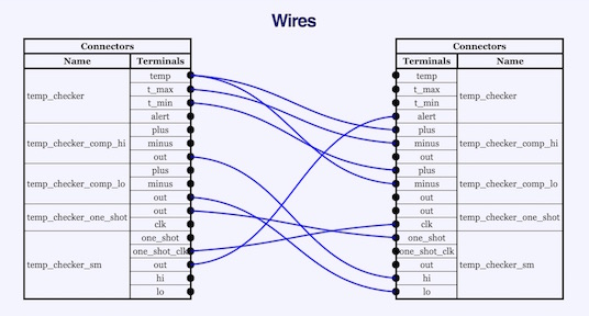
Script ListingsAll of our actual Scripts are shown here. Wrap UpOur system has been up and running for a few months. So far, we've had only two minor issues. One was our Gmail messaging became unreliable. Near as we could tell, sometimes Gmail didn't want to talk to us. We changed our polling interval from 5 minutes (300 seconds) to 8 minutes (480 seconds), and our messaging has been reliable. The second issue we had was a wet basement alarm one morning - no one noticed it. Early on, the system only sent one message after sensing wetness. We got the message when we were all sleeping, and no one woke up. We changed the system so we now get a message every 10 minutes for as long as there's a problem. Hopefully, we'll wake up next time there's an early morning message. Fortunately, our wetness alarm wasn't due to a real problem - the water was only barely touching our sensor and nowhere else. We built our whole system (UPS not included) for about $260 in parts. |
Catalina Computing, LLC.Copyright © Catalina Computing, LLC. (2013-2018) 
|
Page last updated: Mon Jun 8 22:40:38 2015 (UTC) |

