|
|
Projects << LowCostAlarmProject | Software Overview | Sitemap | Downloads | Developers | Forums |
|
|
Low Cost Alarm ProjectIn this project, we'll be building a low cost alarm system. When we say low cost, we mean building a complete system for a little less than $100. Alarms will send text and/or email messages. The system will respond to messages as well. You can query it for status, reset it, or turn it off and on using email and/or text messages. We'll build a simple system which monitors a door or window sensor. The system will be extensible, so it can monitor many other kinds of sensors. You can customize it for your own needs. Choosing a HostTo run your system, you'll need a host. If you've already got a Linux machine or Mac running 24/7, you can use it as your host. If you don't, an inexpensive option is using a Raspberry Pi computer. You'll need a Pi, a Pi case, a USB power supply, and a compact flash boot disk (4GB or more). You can buy these many places on the internet. At the time of this writing, you can buy everything for less than $60. If you prefer, you can buy a different Linux or Unix-like host, but at this time, Pi systems are among the least expensive. 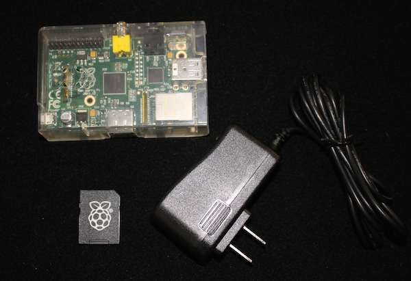
Choosing SensorsTo get started, we'll build an alarm system with a "normally closed" door/window switch. Whenever a door or window opens, we'll get an alarm message. Door/window switches have 2 components - one which mounts to the door/window and one which mounts right next to it on the door or window frame. The component on the door/window has a magnet inside of it, and the other component has a switch. When the magnet is near the switch, a "normally closed" switch is in the closed or "on" state. If the magnet is more than an inch or so from the switch, the switch opens. 
Door/window switches are easy to find on the internet. Look for "magnetic alarm switch". Normally Open (NO), Normally Closed (NC) SwitchesAlarm system switches, like the door/window switch, come in two flavors - normally open (NO) and normally closed (NC). The flavors describe whether the switch is (normally) closed (shorted/on) or open (off) when it's not in the alarm state. So a NC door/window switch will be closed (in the on state) when its door or window is closed. We'll be using NC switches in our system, because they have some desirable properties. One is they can be chained together. If you wire them in series, a chain, they act like a single switch, which goes from closed to open when any one switch in the chain opens. So you can have lots of NC sensors in a system while only requiring one set of sense inputs for the whole chain. They can make your wiring job easier, since wires can go from one switch to the next rather than back to your controller each time. Another useful property is cut wires cause alarms. Since a cut creates an open in the switch circuit, a cut wire will create an alarm, just like the switch would. If you break a wire or a bad guy tries to defeat your system by cutting one, you'll get an alarm. Choosing an I/O InterfaceWhen we install our sensors, we'll need to connect them to our host system. If you are using a Raspberry Pi, your host already has I/O headers built into it. Other hosts may have I/O pins as well. We won't be using these for our Alarm system however. Generally, when signals like our sensor wires run over long distances, we consider these signals dangerous. Not dangerous to people, but dangerous to our host. If static electricity jumped onto one of these wires (which it easily could), the signal would probably kill our Pi. Instead, we'll connect our sensors to a board which is a bit tougher and with some interesting capabilities. We'll be using a DLP IO8-G for our I/O. It has 8 general purpose pins capable of doing digital input and output, sensing analog voltages, and measuring temperature. It's also very reasonably priced (at this time, about $30). 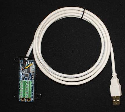
Installing the HardwareFind a suitable spot for your Raspberry Pi. It will need to be near a power outlet and need access to Ethernet. The location will need to have enough room for your Pi and your IO8-G device. The IO8-G has mounting holes, so you can screw it onto something. Most Pi cases also have mounting holes as well (and you can always drill a couple if yours does not). Put your Pi and your IO8-G devices someplace where they won't fall, and where they'll be free from dust and debris. Though the Pi and IO8-G don't use a lot of power, they should be someplace with moderate air flow or cooling. Ideally, the Pi should be in a spot which makes sensor wiring easy. 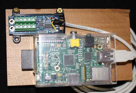
Mount your door/window sensor to your door or window of choice - we'll be putting it on a door. Put the magnet on the door/window at a spot where it can be next to the switch when the door/window is closed, and well away from it when opened. Mount the switch to a door frame or window frame right next to the magnet. There are two screw terminals on the switch. Connect one end of a twisted pair of wires (a wire pair from an Ethernet cable, a phone cable, or doorbell wiring will work) to your switch's screw terminals. 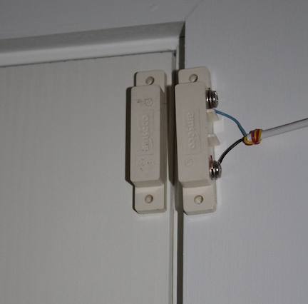
Run the other end of your twisted pair wires back to the IO8-G device. Connect one wire of the pair to the IO8-G "GND" screw terminal and the other wire to the IO8G "1" screw terminal. It doesn't matter which wire goes to the "1" or "GND" screw terminal, just wire one wire to each. Lastly, we need to add a pull-up resistor to the IO8-G "1" screw terminal. The IO8-G "1" input measures digital highs and lows. We want it to measure a digital "high" (an "on") when there's a wire cut or the NC door/window sensor opens, so we are pulling the "1" screw terminal up with a resistor. The resistor pulls the "1" input high when nothing is driving it. Use any 1K to 2K resistor (you can buy these on the web or at Radio Shack) to pull up the "1" screw terminal. Connect one end of the resistor to your IO8-G "1" terminal and the other end to the IO8-G "5V" screw terminal. You'll need to share your "1" screw terminal between your twisted pair wire and your resistor. Loosen the "1" screw terminal, stick the wire and resistor lead into it, and tighten it back down. Give the resistor and wire a slight tug to be sure they are snug. 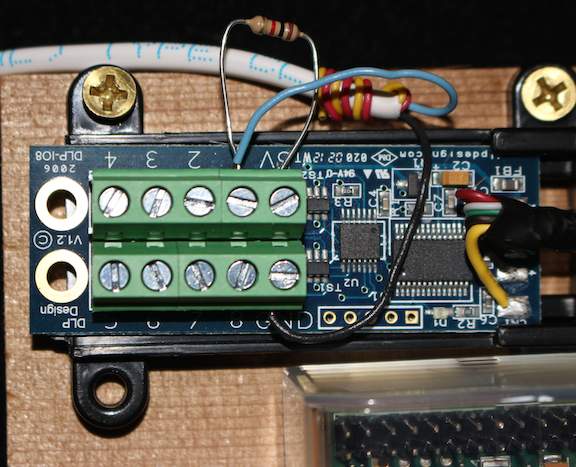
Plug your IO8-G into one of your Pi's USB ports. Plug an Ethernet cable from your network into the Pi and power up your Pi. Your hardware installation is complete. Installing Virtual WiringWe'll be running our alarm system using the Virtual Wiring System. To install Virtual Wiring on your host, download and install the software from the website. If you are installing onto a Raspberry Pi, this HowTo may be helpful. These more general installation instructions may be of use for other systems. Configuring Your Alarm SystemOnce your hardware has been set up and you have Virtual Wiring running on your Pi, you can define your alarm system. Before getting started, get yourself a new email account. When the system senses alarm conditions, it will email or text you from this account. When you control your system, the system will be receiving text and email messages from this account. After receiving messages, your system will be deleting them from the account, so make sure you don't have email in this account you want to save. You've been warned - all email messages in this account will be deleted. Set Up the EmailerYou can use any email account. The name and password can be anything you want. Here, we'll assume we have a Gmail account on Google with user name "alarm_system" and password "alarm". We'll create a TextMessaging email Device which sends and receives email using the account. We'll create the email Device by running a Script. From your Pi's Scripts page, click on the "View Filter" button at the top of the page and select "EMail". In the list of Scripts, find the TextMessagingPOP Script and click on its "Run" action. You'll see a dialog box. Fill in the fields as show below. You'll need to use your own email account user name and password, and your own messaging address ("email_address"). If you are not using Gmail, set gmail_polling to 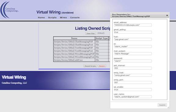
Here are the parameter values shown above in plain text:
Messages will be sent and received by a Verizon smart phone with phone number 999.555.1212. You'll need to put your messaging device's email address in the Set Up the IO8-GTo configure your IO8-G, you'll need to know what your computer calls the device. From a command prompt on your host system enter: To set up the IO8-G, we need to create an IO8-G Device. We create it by running a Script. From your Pi's Scripts page, click on the "View Filter" button at the top of the page and select "DLP". In the list of Scripts, find the IO8 Script and click on its "Run" action. You'll see a dialog box. With your IO8-G device name in hand, fill in the fields as show below. The "port_location" parameter is your IO8-G device name.
The poll_interval determines how often the Virtual Wiring system polls the IO8-G Device. We want a 1 second value here, so someone can't quickly open a door and close it before Virtual Wiring senses it. Virtual Wiring Software versions 1.5.0 and below will poll at intervals no less than 10 seconds apart (though they will not complain if you set a shorter interval). For 1 second polling, use versions 1.5.1 and above. Set Up the Alarm DeviceTo run the alarm system, we use an Alarm Device. The Alarm Device checks the sense terminals from the IO8-G, sets various alarm output terminals, and sends messages to the TextMessaging Device. We create the Alarm Device by running a Script. From your Pi's Scripts page, click on the "View Filter" button at the top of the page and select "Alarm". In the list of Scripts, find the Alarm Script and click on its "Run" action. You'll see the Script needs a "duration" parameter. The duration is the time in seconds we want the alarm to stay on. Here, we'll let it stay on for one a second. If we wanted the alarm to turn on a siren, we might want it to last a few minutes to scare an intruder away. You also might like to make the duration longer, so you don't get a lot of text messages. The Alarm Device sends a message each time it signals an alarm. You could set the duration for a few hours (<a few hours> * 60 * 60 seconds), so you would get a message the first time your door opened, but no more unless the door hadn't opened for a few hours. Run the Alarm Script with these parameters:
Next, since we've mounted our sensor to a door, we'll define a "door" input on our Alarm Device. The "door" input will connect to our IO8-G Device's door/window sense output. We'll tell the Alarm to trigger on the "door" input when it is Run the Equal Script in the InputTypes directory of the Alarm directory (you should see it in your list of "Alarm" Scripts). The "alarm_id" parameter is the name of our Alarm Device (we called it "alarm").
Our Alarm Device is ready to go. Wire Things Together, VirtuallyUsing the Virtual Wiring system, we've built a TextMessagingPOP Device, an IO8-G Device, and an Alarm Device. Now we are going to wire them together. The door/window sense terminal on the IO8-G needs to connect to the "door" terminal of the Alarm Device. The messages from our Alarm Device need to go to our TextMessagingPOP Device, and messages from our TextMessagingPOP Device need to go to our Alarm Device. 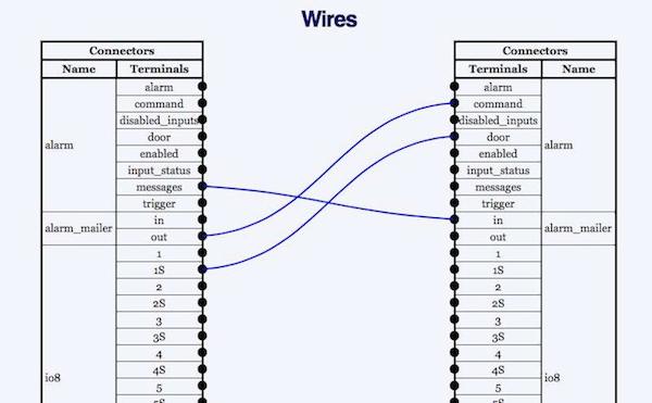
Above is the wiring diagram for the system. We've drawn wires on the Wires page connecting the Devices together. Since we connected our door/window sensor to the "1" screw terminal on our IO8-G, we connect the IO8-G Device pin 1 status terminal, "1S", to the "door" terminal of the Alarm Device. The "messages" terminal of our Alarm Device connects to the "in" terminal of our TextMessagingPOP Device, and the TextMessagingPOP "out" terminal connects to the "command" terminal of the Alarm Device. Using our messaging device, we can send and receive messages to and from the Alarm Device. Save It!We are done building our system, so we need to save our work. If you look at the Console page, you can see all we've done along with the results of our commands. We are going to copy our work into a Script we'll call "alarm_system.script". Then we can run that Script whenever we wish to create our alarm system. First we'll create the "alarm_system.script" Script file. We'll put the file in our "Scripts/user" area. For security reasons, we can't create files using the Virtual Wiring system, so we'll do it from the command prompt. Open a terminal screen on your host system. "cd" to the top level directory of your Virtual Wiring installation. From there type: After creating the Script file, we need Virtual Wiring to see it. Virtual Wiring keeps a Script cache (for performance reasons), so it won't see external changes to our Script files until it restarts. From the Virtual wiring Console, type: Next we'll copy our Console into our "alarm_system.script" Script. Go to the Console page and select all the lines from our session (if you started from a clean Console, that's all the lines in the Console). Copy them, and go the the Scripts page. At the top, click on the "View Filter" button and select "user". In the list of Scripts, find the "alarm_system.script" and click on its "Edit" Action. Paste the copied lines from the Console into the Script. Delete the lines that are command responses, the status lines, and keep the command lines. Delete any commands your don't want (if you copied the 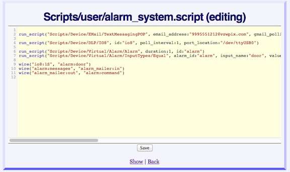
Click here to see the complete text of the "alarm_system.script". Note:
Since we restarted our system after creating the "alarm_system.script" (see above), our alarm system is no longer running. Click on the "Run" action of "alarm_system.script". Our alarm system is restored. You can run the "alarm_system.script" anytime you want to create your alarm system (just make sure you've plugged in your IO8-G, or the Script will fail). Testing Things OutIf you've completed all the installation steps, your system should be up and running. Try opening and closing your door/window a few times. Each time the door/window opens, you should get a message which looks something like: Try getting your system to respond to a message. Reply to one of your Alarm messages with one of the Alarm Device Commands. Send a message containing only the word If you want to experiment with your system more directly, go to the Device Explorer page. Look at terminals and their values. Try clicking on terminals and entering new values. 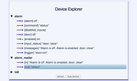
Wrap UpWe've built an Alarm system which sends alerts using messages. We can also send messages to turn it on and off, reset the alarm, and get status. Here are a few more enhancements you might like. Automatic StartupOur system runs when we run the "alarm_system.script". Perhaps you want this script to run automatically, every time you start Virtual Wiring. To do this, we will run the Script from the "startup.script". Go to the Scripts page, click on the "View Filter" and select "user". Open the "startup.script" Script by clicking on its "Edit" action. Add the line:
Now your alarm system will run each time you run Virtual Wiring. To get Virtual Wiring to run each time your Pi boots up, open your Pi's /etc/rc.local file and add a line like:
The rc.local file runs each time your Pi boots. We've added a line to run Virtual Wiring. You'll need to make the "cd" path be the location where you've installed Virtual Wiring. That's it. Your alarm system will start running every time your start your Pi. Adding More SensorsWe've got 7 unused terminals on our IO8-G that can measure digital inputs, analog inputs, and temperature; we've also got a NC door/window sensor circuit to which we can add more normally closed sensors. What else do you want to add? A low/high temperature alarm? A motion sensor? A moisture detector? Go for it! Is your DLP IO8-G terminal block getting crowded? Look at our terminal expander board. |
Catalina Computing, LLC.Copyright © Catalina Computing, LLC. (2013-2018) 
|
Page last updated: Mon Jan 4 22:52:55 2016 (UTC) |