|
|
Devices << INSTEONDevices | Software Overview | Sitemap | Downloads | Developers | Forums |
|
|
INSTEON DevicesINSTEON devices are popularly used in home automation systems. INSTEON devices are known for using power wires as their means of communication, though many also communicate wirelessly. Common INSTEON devices are wall switches, wall outlets, dimming and switching modules, motion, door and window sensors, and smart thermostats. INSTEON devices are available on the web and at retail stores. See: http://www.insteon.com for information on INSTEON devices. 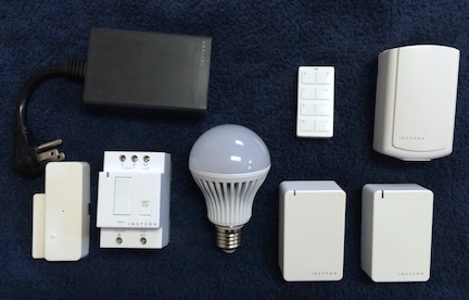
Most modern INSTEON devices communicate simultaneously both over power wires and wirelessly (using radios). INSTEON is a mesh technology, so its range increases as more devices are added to a system. When travelling through power wires, INSTEON devices can communicate through walls and other obstacles. When travelling wirelessly, INSTEON radios have a range up to 150 feet (depending on obstacles). Using power wires, radios, and mesh technology, INSTEON can communicate through walls, obstacles, and in the clear over many hundreds of feet. The INSTEON devices we support are listed here Low Level Configuration of your INSTEON DevicesBefore adding INSTEON devices to the Virtual Wiring System, you need to do some low level configuration. This section describes what this configuration is doing and how to configure your INSTEON devices. INSTEON systems begin with a special device called a modem. The modem plugs into a USB port on the Virtual Wiring system host, and it monitors and controls an INSTEON system. The modem "links" to other devices into the system, and they may optionally "link" to it; a "link" allows a device to tell another device what to do. We use the INSTEON Powerlinc Modem, model number 2413U. 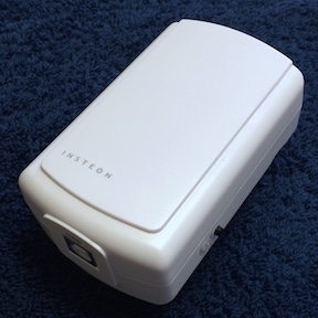
To set up an INSTEON system, purchase a PowerLink Modem and the INSTEON devices you need. We support a number of INSTEON devices; these include all the basic dimmer and simple switch devices (wall switches, outlets, appliance modules, door and window sensors). All the devices we support are described below. Linking DevicesOnce you have purchased your modem and devices, you need to establish "links" between the devices and the modem. Links allow your modem to control devices and your devices to tell the modem what they are doing. Links are uni-directional, so to both control a device and have a device communicate back to the modem, you need a pair of links; one goes from the modem to the device, and the other goes from the device to the modem. Generally, unless you are sure you need only one link (INSTEON light bulbs only have one link going from the modem to the light bulb), it's best to create a pair of links between the modem and each device - one link in each direction. Using INSTEON terminology, the controlling device is called a "controller" and the controlled device is called a "responder", so generally, a modem needs to be both a controller and a responder for each device, and each device needs to be both a controller and responder to the modem. Linking is done when your modem and devices are powered on. The INSTEON modem and devices have a single "link" button on them for creating (and deleting) links. To create a link, press the link button on the controller and hold it (for about 3 seconds) until the controller beeps and its status light starts blinking; then, press the link button on the responder. The responder should beep and the controller's status light should stop blinking. That's it - you've created a link from the controller to the responder. To create a link in the other direction, treat the controller as the responder and the responder as the controller and repeat the procedure. Once you've put your controller into link mode, you'll have about 4 minutes to link to its responder. If you don't create a link in time, the controller will drop back into its normal, non-linking mode. Note: INSTEON light bulbs may not have a link button. To complete a link to a light bulb, leave the bulb powered off when pressing the controller's link button. Once the controller beeps, screw in (or otherwise turn on) the light bulb, and it will complete the linking process. Unlinking DevicesFrom time to time, you may need to remove devices from your INSTEON system. When you do, you need to delete their links. Deletion is similar to creating links, except to put your controller into delete mode, you first need to put it in create mode (by holding its link button until it beeps), and then hold its link button again until it beeps a second time. You'll know it's in delete mode, because its status light will blink faster. Then select the responder by pressing its link button, and the link from the controller to the responder is deleted. If you have links in both directions, Repeat the procedure using the controller as the responder and the responder as the controller. Note: linking and unlinking is described on the INSTEON website and in your INSTEON device's documentation. If the methods described above do not work for you or you have unanswered questions, read the INSTEON documentation. Installing INSTEON Devices in the Virtual Wiring SystemTo use a device in the Virtual Wiring system, it must be installed. If you haven't already, begin by linking your INSTEON devices and modem together. Next, install the INSTEON Modem into the Virtual Wiring system. Once the modem is installed, you can install the other devices. The modem and the other devices are all installed by running their Device Scripts. INSTEON AddressesWhen installing a non-modem device, you will need a parameter called the INSTEON Address. The Address uniquely identifies the device in an INSTEON network. On each INSTEON device, there is a label of the form XX.XX.XX, where the Xs are either the digits 0-9 or the letters A-F. A label might read: Run the Device ScriptsWith your modem installed and your INSTEON Address(es) in hand, you are ready to install your remaining INSTEON Devices. Install each Device by running its Device Script. The Device Scripts are fully described in the Supported Devices section. As you successfully install your INSTEON Devices, you may want to copy the installation commands from the Console or the Session Script into a Script. Once the commands are Scripted, you can run them by just clicking on the Script. If you choose, you can put the commands into your startup Script, so they are run each time your start or restart your system. Supported INSTEON DevicesThe following INSTEON Devices are supported by the Virtual Wiring System. For installation instructions and additional information, see the following sections.
|
Catalina Computing, LLC.Copyright © Catalina Computing, LLC. (2013-2018) 
|
Page last updated: Sun Apr 30 20:20:26 2017 (UTC) |