|
|
Tutorials << WiredInvertersTutorial | Software Overview | Sitemap | Downloads | Developers | Forums |
|
|
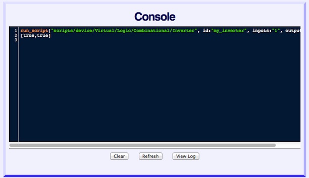
Wiring 2 Inverters TogetherIn the previous tutorial, we created an Inverter called "my_inverter" and applied an Rather than use the Scripts page to create an Inverter, we'll use the Console to create a second Inverter. We'll call this Inverter "inverter2". We'll use the Console to create "inverter2", because it's a little quicker, and creating an Inverter this way will demonstrate using the Console. Click on "Console" at the top of the page. If you did the previous tutorial, you should see something like this:
Next, click on the line,
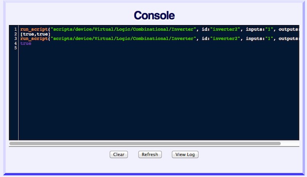
, and move the cursor right between the "r" and the double quote of "my_inverter". Now use the delete key on your keypad to delete "my_inverter" and replace it with "inverter2". Your new line should look like:
Place the cursor at the end of your edited line (just after the closing parenthesis), and hit return. Wait a moment, and you should see this:
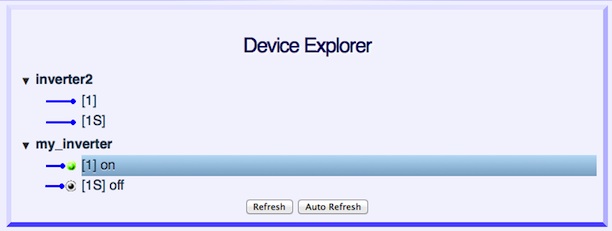
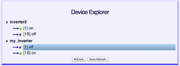
You see the line you edited followed by the command you just entered. That's OK, but the Console no longer reflects an accurate history of the system. You actually created 2 Inverters with IDs "my_inverter" and "inverter2". Because the screen was edited (to save typing), it no longer has an accurate history. Click on the "Refresh" button at the bottom of the screen, and you should once again see the history accurately. Now go to your Device Explorer page by clicking "Home" at the top of your page. You should see 2 Inverters, "inverter2" and "my_inverter". Click on the expander on "inverter2", so you can see its terminals. Your screen should look like this:
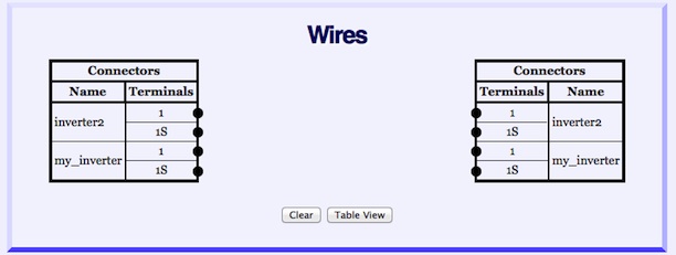
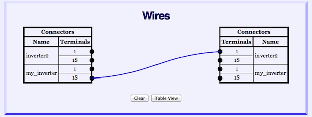
Next, we will wire the 2 Inverters together. Click on "Wires" at the top of your page. You will see the Wires page with a "punchblock" view of your two Inverters. There are two terminal blocks, each with all the terminals of your 2 Inverters.
We are going to connect the output of "my_inverter" (terminal "1S") to the input of "inverter2" (terminal "1"). Terminals are those little black balls on the left and right sides of the terminal blocks. Click on left terminal block, "my_inverter", terminal "1S" and hold while moving your mouse to right terminal block, "inverter2", terminal "1". As you move your mouse to the right, you should see a wire following it. If you don't, try again, clicking just to the left of the center of terminal "1S". While holding down the mouse, move it, and the wire, so both are on top of right terminal block, "inverter2", terminal "1". Release the mouse. You should see a wire that looks like this:
If your wire isn't right, delete it. Delete the wire by clicking on it and clicking on "OK" in the delete dialog box. You should now have a Virtual Wire between the two Inverters. It acts much like a real wire, transmitting whatever values are on the output of "my_inverter" to the input of "inverter2". Go back to the Device Explorer page and click on "my_inverter", terminal "1". You will get a value dialog box. Type in the value
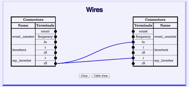
The If you want to delete your wire, go back to the Wires page, click on the wire, and click on "OK" in the delete dialog box. An ExperimentIf you want to try something a little different, draw a wire from "my_inverter", terminal "1S" to "my_inverter" terminal "1". You are wiring an Inverter's output to its input. If you wired a real inverter up this way, it might oscillate and perhaps overheat. It oscillates because it keeps inverting whatever its output value is, which causes its output to change again. Our Inverter is a Virtual Device, so it won't overheat. However, it will oscillate. After drawing your wire between Inverter input and output, click the "Refresh" button at the bottom of the Device Explorer page. Anything changing? Check your CPU's activity level (the "top" program is a popular way to do this on *nix systems). Is the CPU busy? To create an oscillation, your system needs a poke. After you drew your wire, there have been no new events from the Inverter output, so the input hasn't seen anything to invert. On the Device Explorer page, click on the Inverter output and enter an Click on the "Refresh" button a few times and check your CPU's activity level. You should see the Inverter's value changing and your CPU should be very busy. This may get annoying as your computer may get sluggish and your CPU's fan may turn on (lower powered systems may just get sluggish). Go to the Wires page and delete your wire to stop the oscillation. An Experiment: Measuring CPU PerformanceYou can get a relative measure of CPU performance by measuring the output frequency of an oscillating Inverter. Since Virtual Devices, such as the Inverter, run entirely inside their host computer, if one asks an inverter to run as quickly as it can (which happens when an Inverter's output and input are wired together), its speed will be a function of the host computer's performance. The faster the oscillation frequency, the faster the host computer. There is a Virtual Device called an EventCounter which can measure how many events and events per second are appearing on its input terminal. If one connects an EventCounter to an oscillating Inverter, one can see how fast the Inverter is oscillating. To create an EventCounter, go to the Scripts page and set the "View Filter" to "Virtual". Find the "EventCounter" Script and run it. The Script needs an ID parameter, but nothing else. Make up an ID for the EventCounter, we chose "event_counter", and submit it to the system. The EventCounter has an "in" input which counts events and measures their frequency. It has two outputs. The "count" output is the total number of events it has seen. The "frequency" output is the event frequency it is seeing. After creating the EventCounter, go to the Wires page and wire "my_inverter" and the EventCounter as shown below.
The Inverter's input is wired to its output, so it will oscillate. The output of the Inverter is also wired to the EventCounter, so the EventCounter will count events and measure their frequency. Once you have your system wired, give an Inverter terminal (or the EventCounter "in" terminal) a poke to
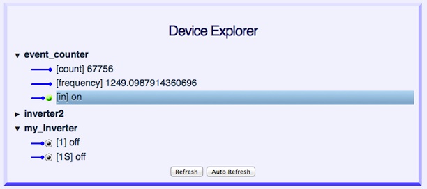
Hit the "Refresh" button a few times to get a feel for the event frequency of the oscillator. Note in the screen shot, the "in" input of the EventCounter is not the same value as the Inverter terminals. While the system was in the midst of refreshing the "Device Explorer", some terminals changed value. Though the internal Virtual Device system is locked and synchronous, the Explorer learns device terminal values by making a series of asynchronous "peeks". As a result, not all the terminal values it displays happened at exactly the same time. Not a problem, and rarely visible in systems generating relatively few events per second. In systems which are are generating events near their maximum rate, it's hard for the the Explorer to peek fast enough capture a consistent state across all the devices. When you are done, remember to delete the Inverter's input to output wire to stop the oscillation. As an alternative, you could always do a Restart from the bottom of the Scripts page. We ran our test on an old MacBook Pro. We've also run it on some small embedded computers running Linux, and they generated about 50 events per second. Here are some results we've collected from various systems: |
Catalina Computing, LLC.Copyright © Catalina Computing, LLC. (2013-2018) 
|
Page last updated: Thu Mar 23 19:42:23 2017 (UTC) |