|
|
Projects << INSTEONAlarmProject | Software Overview | Sitemap | Downloads | Developers | Forums |
|
|
INSTEON Alarm ProjectHere we describe how we built an entire alarm system using INSTEON devices. What's unique is all its components install in minutes, because they are wireless. Also, it's just about impossible to defeat (if you can keep power running and an internet connection); no matter what you do, it's going to notify somebody there's something going on. BackgroundWe built our system in a home where the owner was worried about a series of neighborhood break-ins. She wanted to know when someone entered her house, so she could take whatever action was necessary. She also wanted the system to be dead simple - no confusing codes or button sequences. Lastly, she liked the idea of being notified on her cell phone. Depending on the time of day, she'd know if it might be her kids, her husband, or someone who shouldn't be there. If she wasn't sure, she could call home and see who answered. If no one answered, she could call a neighbor, a friend, or the local police. Basic DesignWe wanted the system to be dead simple to operate. After puzzling over what would be simplest, we decided a 2 button system would be the simplest. One button would enable the alarm system, and one button would turn it off. The system would notify users of alarms and status using email and text messages. As for button placement, we'd put the enable button right near the front door, so it would be easy to remember to push it. We'd hide the disabling button, but not too cleverly, because as you'll see, it doesn't need to be well hidden. Any alert would be sent to a user definable group of cell phone numbers and/or email addresses. In case someone forgot to turn on the system, the system could also be enabled (and disabled) by cell phone or email. 
All actions (motion, open/closings, enabling/disabling the system) would send a message to all the enlisted cell phones and email devices. So every button push would send a message telling the state of the system and, if the system were enabled, all the intrusion sensors would also send messages. One of the reasons the system is so simple is it doesn't need to have fancy codes or hidden buttons; even if a bad guy knew exactly how the system operated, he'd still have to disable it with a button push, and that would generate a message and notify the owner. And if the owner wanted, she could re-enable it with a text message or an email. Even if a bad guy knew where the buttons were and destroyed them, he wouldn't be able to get around the system. Since the buttons are wireless and independent of the sensing and alarm generation parts of the system, destroying them would only make it to impossible use them - it wouldn't stop the rest of the system from functioning. Component SelectionTo build the system, we chose a Raspberry Pi and INSTEON components. Using all INSTEON components made the system easier to purchase (one stop shopping) and set up (the INSTEON components are wireless). System ControllerFor the controller, we used a Raspberry Pi. Raspberry Pis are robust and low cost; at this time, you can set up a complete Pi system (Raspberry Pi, case, flash disk, power supply) for around $50. In addition, Raspberry Pis have lots of flexibility - you can easily share the Pi in this project with many other projects, simultaneously. We used a Raspberry Pi 2 Model B, as it's the fastest Pi available at this time, and it's still quite inexpensive. We put our Pi in a plastic case (a Multicomp enclosure we purchased from Element14) and powered it with a Raspberry Pi 2 Amp universal power supply (the "official and recommended" supply for Raspberry Pis), and a 16GB compact flash disk. On the disk, we installed NOOBs, and then we installed Raspbian (a popular Linux for Raspberry Pis). INSTEON ModemSince the alarm system is INSTEON based, we needed a modem to talk to the INSTEON devices. For the modem, we plugged an INSTEON 2413 Modem into one of the Pi's USB ports. The 2413 modem connects the Pi to both wired and wireless INSTEON devices. Though we will only use wireless INSTEON devices in this system, you can add your own wired INSTEON devices. You can also plug any Dual-Band (wired and wireless) INSTEON device into an outlet far from you modem and extend your wireless range. 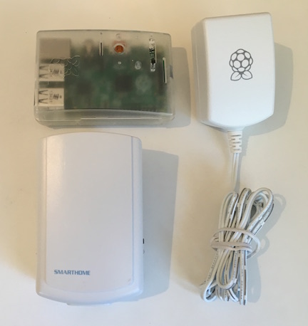
SensorsWe used 2 INSTEON Open Close Sensors to sense our on and off buttons - one for each button. We used a single INSTEON Motion Sensor to detect intruder motion. If your installation needs more than one motion sensor, you can add more pretty much without limit; how to do this will become clear in the Configuration section. ButtonsAs on and off buttons for the system, you can use any normally open type of push button. We used 2 brass doorbells we bought from Amazon. With small configuration changes, you could use most any other type of button or switch as well. SummaryWe used the following components.
Note: your sensors will need batteries; if you buy them new, they should come with batteries. Installing the HardwareInstalling the Raspberry PiFind a suitable spot for your Raspberry Pi. Your Pi should be running running Raspbian Linux. It will need to be near a power outlet and need access to Ethernet. Most Pi cases have mounting holes, so you can mount your Pi to a surface if you'd like. Put your Pi someplace where it won't fall, and where it will be free from dust and debris. Though the Pi doesn't use a lot of power, it should be someplace with moderate air flow or cooling. Plug an Ethernet cable into your Pi. Plug in your Pi's power supply and connect it to your Pi. Installing the INSTEON 2413 ModemPlug your INSTEON 2413 Modem into an unfiltered outlet (so wired INSTEON signals are not filtered out) near your Pi. Use a USB cable to connect your modem to your Pi. Installing the Motion Sensor(s)Before placing the Motion Sensor in its final resting place, you will need to "link" it to your INSTEON Modem. Detailed information about linking is available on the INSTEON site, but what linking does is tell your Motion Sensor and Modem about each other's existence, and tell the sensor who to notify when it senses motion. INSTEON linking is done by pressing, holding, and releasing an INSTEON Controller's link button, and then pressing, holding and releasing an INSTEON Responder's link button. The Controller is what senses things (here, your motion sensor), and the Responder is what gets notified (here it will be your INSTEON 2413 Modem). Open your motion sensor's case and press and hold its link button until it's linking LED starts blinking. Bring the sensor near to your Modem and press the Modem's link button until the Modem gives a small grunt and the motion sensor stops blinking. You're done - your devices are linked. Before closing up your motion sensor, note and write down its INSTEON address (written on an inside label with 3 pairs of digits or A-F separated by periods, e.g. 12.C4.AD) for later use. Find a suitable spot for your INSTEON motion sensor. Ideally, it should face an area where an intruder is most likely to travel. Place it wherever you need it. If you need more than one motion sensor, link and place additional ones where needed. Installing the On and Off ButtonsWe'll be using push buttons to turn our alarm system on and off. To connect our buttons to our INSTEON system, we'll use 2 INSTEON Open/Close Sensors. The Open/Close Sensor has 2 screw terminals which we use to connect our doorbell buttons. To connect a button to an Open/Close Sensor, open the Sensor and locate its two screw terminals. Find yourself a twisted pair of wires (you can find 4 twisted pairs inside an Ethernet cable) of whatever length you need to run between your button and your Open Close Sensor (our wires are about a foot long). Connect the two wires on one end of your twisted pair to terminals in your sensor, and connect the 2 wires on the other end of your pair to your button. 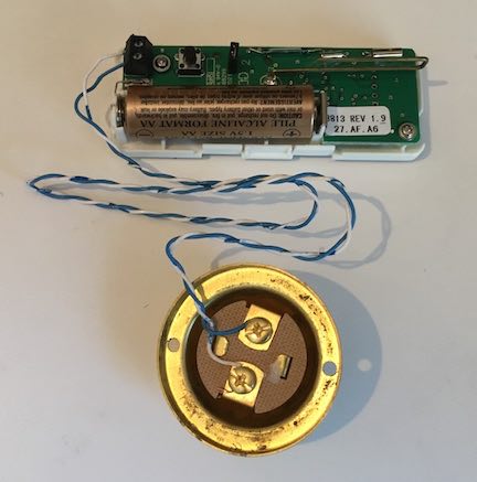
Before placing the Open/Close Sensors in their final resting places, you will need to "link" them to your INSTEON Modem. Linking an Open/Close Sensor is done the same way as described above when linking Motion Sensors. The Open/Close sensor will be the Controller, and as before, the Modem will be the Responder. Before closing up your Open/Close Sensors, note and write down their INSTEON addresses (writen on an inside label with 3 pairs of digits or A-F separated by periods, e.g. 12.34.AD) for later use. Close up your sensor. Repeat the procedure for your 2nd button and Open/Close Sensor. Next, place your buttons and sensors someplace handy. Typically, the "on" button is easily visible somewhere near where you will be exiting. Hide the "off" button, but put it somewhere where you can easily get to it. As we explained, even if an intruder finds your "off" button and presses it, you'll still get a message telling you someone has turned the system off. Note: the On/Off Sensors come with a magnet, so they can be triggered when something opens or closes. Since we are using the sensor to sense button pushes, there is no need for the magnet. Put your 2 magnets for the 2 sensors someplace safe, so you can use them in some other project. A Note about Installing Wireless INSTEON DevicesWe've found the range of our wireless sensors is reliably somewhere around 20 feet when there is little to moderate interference (not going through thick walls or metal objects). Though wireless INSTEON devices can go further if their signal path is clear, we've found that our motion detectors and on/off buttons often have a person in front of them when they are transmitting. That person will block signals and diminish the range. If you find any of your wireless devices are not transmitting reliably, try plugging in a Dual-Band INSTEON device somewhere near it (we often use INSTEON On/Off Switches, Dimmers, or Range Extenders). Dual-Band devices will receive wireless transmissions and inject them into your location's electrical wiring, so signals can reach back to your modem. If placing a Dual-Band device near your sensor doesn't improve your reception, make sure the phases of your electrical wiring are bridged (easy to do with another Dual-Band device). To learn more about bridging, visit the INSTEON site Installing Virtual WiringWe'll be running our alarm system using the Virtual Wiring System. To install Virtual Wiring on your Pi, download and install the software from the website. Then follow the HowTo to install Virtual Wiring on your Pi. Configuring Your Alarm SystemOnce your hardware has been set up and you have Virtual Wiring running on your Pi, you can create your alarm system. Before getting started, get yourself a new email account. When the system senses alarm conditions, it will email or text you from this account. When you control your system, the system will be receiving text and email messages from this account. After receiving messages, your system will delete them from the account, so make sure you don't have email in this account that you want to keep. You've been warned - all email messages in this account will be deleted. Set Up the 2413 ModemTo set up your 2413 Modem, you'll need to know what your computer calls the device. From a command prompt on your host system enter: To set up the Modem, we need to create a 2413 Modem Device. We create it by running a Script. From your Pi's Scripts page, click on the View Filter button at the top of the page and select "INSTEON". In the list of Scripts, find the Modem2413 Script and click on its "Run" action. You'll see a dialog box. With your Modem's device name in hand, fill in the fields as shown below and submit them. The "port_location" parameter is your Modem's device name.
Set Up the Motion Sensor(s)To set up the Motion Sensor(s), we'll use an INSTEON Motion Sensor Device. The Motion Sensor Device turns its 1S (terminal 1 status signal) on and off as it senses or doesn't sense motion. We'll create the Motion Sensor Device by running a Script. From your Pi's Scripts page, click on the View Filter button at the top of the page and select "INSTEON". In the list of Scripts, find the MotionSensor Script and click on its "Run" action. You'll see a dialog box with an id:, port_location: and address: parameter. The ID is what we will call our sensor, and the address is the INSTEON address value we wrote down before we closed up the sensor. We won't need to supply a port_location value, so we'll just accept the default value. For a Motion Sensor with an INSTEON address of 2D.41.55 and an ID of "motion", we run the MotionSensor Script with the following parameters:
If you have more than one motion sensor, rerun the MotionSensor Script for each sensor, giving each a different ID and address. Set Up the Open/Close SensorsTo set up the Open/Close Sensors, we'll use an INSTEON Open/Close Sensor Device. The Open/Close Sensor Device turns its 1S (terminal 1 status signal) on and off as it senses no push or pushes on its push button. We'll create an Open/Close Sensor Device by running a Script. From your Pi's Scripts page, click on the View Filter button at the top of the page and select "INSTEON". In the list of Scripts, find the OpenCloseSensor Script and click on its "Run" action. You'll see a dialog box with an id:, port_location: and address: parameter. The ID is what we will call our sensor, and the address is the INSTEON address value we wrote down before we closed up the sensor. We won't need to supply a port_location value, so we'll just accept the default value. Our "on" button sensor had an INSTEON address of 27.AF.A6, and we decided to call it "on_button". We ran the OpenCloseSensor Script with the following parameters:
For the "off" button, rerun the OpenCloseSensor Script using the other INSTEON address you wrote down and an ID of "off_button". Set Up the EmailerThe emailer is what sends and receives text and email messages for the alarm system. To operate, it needs an email account on an email server. You can use most any email server you want with your own user name and password. In this example, we'll assume we have a Gmail account on Google with user name "alarm_system" and password "alarm"; we'll create a TextMessaging email Device which sends and receives email using this account. We create our email Device by running a Script. From your Pi's Scripts page, click on the View Filter button at the top of the page and select "EMail". In the list of Scripts, find the TextMessagingPOP Script and click on its "Run" action. You'll see a dialog box. Fill in the fields as show below. You'll need to use your own email account, user name and password, and your own messaging address ("email_address"). If you are not using Gmail, set gmail_polling to 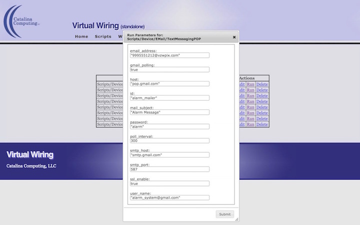
Here are the parameter values shown above in plain text:
Messages will be sent and received by a Verizon smart phone with phone number 999.555.1212. You'll need to put your messaging device's email address in the If you want to add additional users to the system (other cell phones or email addresses which will receive notifications and that can control the system), run the addEmailAddress Script Set Up the Alarm DeviceTo run the alarm system, we'll use an Alarm Device. The Alarm Device checks the sense terminal from the motion sensor, sets various alarm output terminals, and sends messages to the TextMessaging Device. We'll create the Alarm Device by running a Script. From your Pi's Scripts page, click on the View Filter button at the top of the page and select "Alarm". In the list of Scripts, find the Alarm Script and click on its "Run" action. You'll see a dialog box with id:, duration:, and real_time: parameters. We'll use the default duration and real_time values, and give it an ID of "alarm". Run the Alarm Script with these parameters:
With this system, we are going to be deriving our Alarm messages from the input_status terminal of our Alarm Device, so we won't be needing alarm messages on our Alarm Device's messages terminal. There's a command for disabling Alarm messages, and we'll run it here. Go to Console page and type into the Console: Now our Alarm Device will only report results from commands on its command terminal. Next, since we want to monitor a motion sensor, we'll define a "motion" input on our Alarm Device. The "motion" input will connect to our INSTEON motion sensor's output. We'll tell the Alarm to trigger on the "motion" input when it is Run the Equal Script in the InputTypes directory of the Alarm directory (you should see it in your list of "Alarm" Scripts). The "alarm_id" parameter is the name of our Alarm Device (we called it "alarm").
Our Alarm Device is ready to go. If you want to add other motion sensors, you can run the Equal Script once for each of them, each time using a different input_name value. Alarm Devices support an almost unlimited number of inputs. Create a State MachineWe need a small bit of "glue" to tie some of our Devices together. Virtual Wiring has lots of Devices for gluing things together (Logic Devices, State Machines, creating Virtual Devices), and we are going to need a little glue. In particular, we need 3 things. We want to send out status messages from our Alarm Device only when our Alarm Device is enabled, we want our "off" button to generate an "off" commands to our Alarm Device when it is pushed, and we want our "on" button to generate an "on" commands when it is pushed. Using a State Machine, this is pretty easy. Here is the code: So our State Machine is acting like a filter, filtering out unwanted status messages (we don't want to hear about alarm status events if the Alarm isn't enabled), and filtering out "on" or "off" events from our buttons (we want one button to only generate "ons" and the other to only generate "offs". To build our State Machine, we'll first need to create a Script. Go to the Scripts page and select "user" in the View Filter; this will help us create our State Machine Script in the user area. Next click on the "Create a Script" button at the bottom of the Scripts page. You will see a dialog box asking you for your Script name - type in "Scripts/user/alarm_interface.yaml" (unquoted). Submit your dialog box and then click on the Edit action of your new Script. Copy the State Machine code above into the Script and save it. To create the State Machine, click on the View Filter at the top the Scripts page and select "Virtual". Find the "Scripts/Device/Virtual/StateMachine" Script and click on its Run action. You'll see a dialog box with file_name:, id:, and table_name: parameters. Leave the table_name: parameter as it is and type in "alarm_sm" (quoted) for the ID, and "Scripts/user/alarm_interface.yaml" (quoted) for the file name. Submit the dialog box. You've created the State Machine. Wire Things Together, VirtuallyUsing the Virtual Wiring system, we've built a Modem, a TextMessagingPOP Device, an Alarm Device, a MotionSensor Device, 2 OpenCloseSensor Devices, and a StateMachine Device. Now we are going to wire them together. The 1S sense terminal on the MotionSensor needs to connect to the "motion" terminal of the Alarm Device. The status messages from our Alarm Device need to be filtered through our StateMachine before going to our TextMessagingPOP Device. Our on/off messages from our buttons need to be filtered through our StateMachine before going to our Alarm Device. Lastly, our TextMessagingPOP Device messages need to go to our Alarm Device (so we can control the Alarm system via email or text messaging). 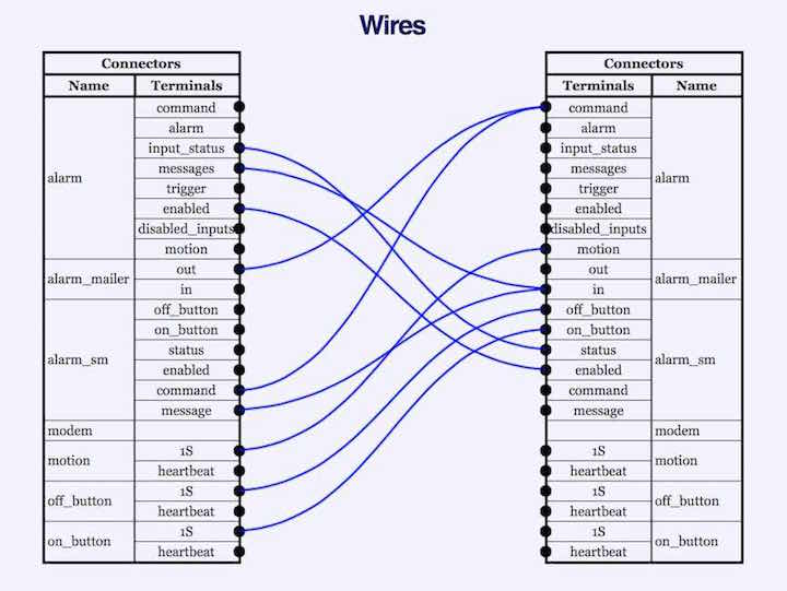
Above is the wiring diagram for the system. We've drawn wires on the Wires page connecting the Devices together. The "message" terminal of our State Machine Device and the "messages" terminal of our Alarm Device both connect to the "in" terminal of our TextMessagingPOP Device, so we get filtered messages about alarms and messages when the alarm is turned on and off. Save It!We are done building our system, so we need to save our work. If you look at the Session Script page, you can see all we've done thus far. We are going to copy our work into a Script we'll call "alarm_system.script". Then we can run that Script whenever we wish to recreate our alarm system. First we'll create the "alarm_system.script" Script file. We'll put the file in our "Scripts/user" area. Go to the Scripts page and select "user" in the View Filter; this will help us create our Script in the user area. Next click on the "Create a Script" button at the bottom of the Scripts page. You will see a dialog box asking you for your Script name - type in "Scripts/user/alarm_system.script" (unquoted). Submit your dialog box - you've created your Script file. Next we'll copy our Session Script into our "alarm_system.script" Script. Go back to the Session Script page and select all the lines from our session (if you started with a clean system, that's all the lines in the Script). Copy them, and go the the Scripts page. At the top, click on the "View Filter" button and select "user". In the list of Scripts, find the "alarm_system.script" and click on its "Edit" Action. Paste the copied lines from the Session Script into "alarm_system.script" and click the "Save" button at the bottom of the Scripts page. You've just saved a Script for building our alarm system. 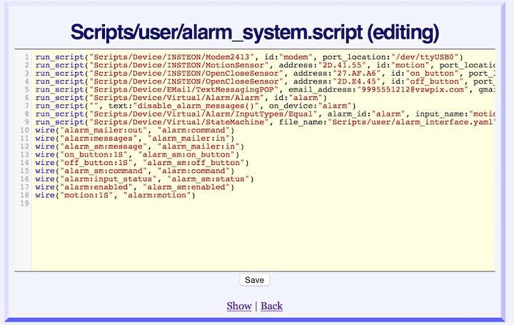
Your saved Script should look a lot like our Script (we've added a few blank lines and comments to make it read better, your email information will be different, your INSTEON addresses will be different, and your Modem's port name may be different). Click the following link to see the complete text of our alarm_system.script. If you ever decide to power down your Virtual Wiring system, you can use your "alarm_system.script" file to recreate your alarm system. Just locate "alarm_system.script" on the Scripts page and click on its run action. All the configuration work we've just completed will be recreated with a single mouse click. Testing Things OutIf you've completed all the installation steps, your system should be up and running. Try waving your hand in front of your motion sensor a few times. Each time motion is sensed, you should get a message which looks something like: After a little period of inactivity, the motion sensor should switch off and you should get a message like: Try getting your system to respond to a text or email message. Reply to one of your Alarm messages with one of the Alarm Device Commands. Send a message containing only the word If you want to experiment with your system more directly, go to the Device Explorer page. Look at terminals and their values. Try clicking on terminals and entering new values. 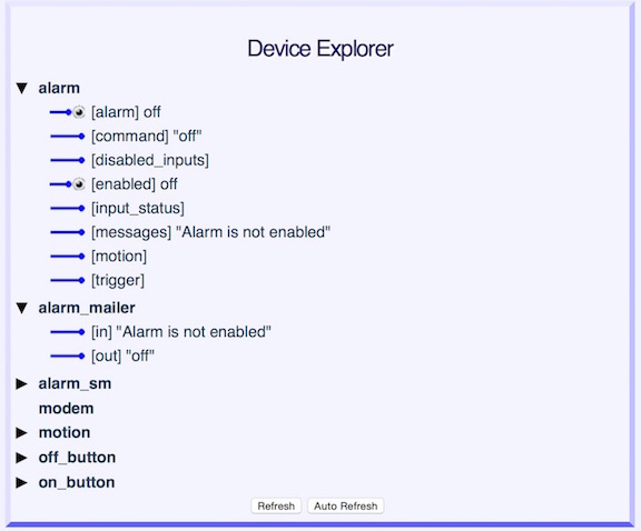
Wrap UpWe've built an Alarm system which sends alerts using messages. We can also send messages to turn it on and off, and get status. Here are a few more enhancements you might like. Automatic StartupOur alarm system is created when we run the "alarm_system.script". Perhaps you want this script to run automatically, every time you start Virtual Wiring. To do this, we will run the Script from the "startup.script". Go to the Scripts page, click on the View Filter and select "user". Open the "startup.script" Script by clicking on its "Edit" action. Add the line:
Now your alarm system will run each time you start up Virtual Wiring. To get Virtual Wiring to run each time your Pi boots up, open your Pi's /etc/rc.local file and add a line like:
The rc.local file runs each time your Pi boots. We've added a line to run Virtual Wiring. You'll need to make the "cd" path be the location where you've installed Virtual Wiring. That's it. Your alarm system will start running every time your start your Pi. |
Catalina Computing, LLC.Copyright © Catalina Computing, LLC. (2013-2018) 
|
Page last updated: Tue Jan 5 21:24:24 2016 (UTC) |