|
|
Devices << BlynkDevices | Software Overview | Sitemap | Downloads | Developers | Forums |
|
|
Devices << BlynkDevices | Software Overview | Sitemap | Downloads | Developers | Forums |
|
|
BlynkAre you looking for a smartphone application for monitoring and controlling your Virtual Wiring system? Want to control a whole bunch of new hardware devices directly from your phone? Blynk Devices may be just what you need. Blynk is a company which makes a smartphone application for controlling devices. The application is unique, because it provides a drag and drop interface for creating your own control interface for controlling and monitoring just about anything. Using just your cell phone, you can create an interface with buttons, sliders, lights, graphs, displays, and gauges. Then you can view your interface on your phone and use it to control and monitor devices. 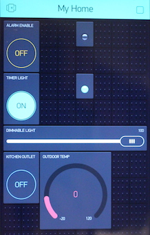
As an added bonus, Blynk provides native code for a large number of popular devices, so you have lots of choices of what you want to control and monitor - Arduinos, Raspberry Pis, and the Sparkfun Blynk Board are some examples. Integrated into the Virtual Wiring system are Blynk Hardware and Bridge Devices. These allow you to control and monitor your Virtual Wiring system using Blynk, and they allow the Virtual Wiring system control other Blynk devices. Getting StartedThe Blynk ApplicationThe Blynk application is a cell phone application which lets you control and monitor hardware devices. Go to the Blynk site and read about Blynk. There, they will tell you how to download and install Blynk on your cell phone. They will also give you a "token". The token is a magic cookie which will let your phone and Virtutal Wiring work within the Blynk system. Once you have your token, design yourself an interface using the Blynk application (for tips, see the instructions on the Blynk website). To get started, try adding one or two of their "widgets" (try a button and an LED). For each widget you add, you will need to define their "pins" (D0, A0, V0, ...). Remember the pins you have chosen, because later, you'll see that these pins will become the names you give to your Virtual Wiring Blynk Device Terminals. When defining your pins, follow the Blynk conventions (D0 is a digital pin, A0 is an analog pin, ...). For now, don't worry about connecting the widgets to any "real" devices - we'll do that in the next section. Virtual Wiring Blynk DevicesOnce you've set up your Blynk application with a widget or two, you define a Virtual Wiring Blynk Hardware Device. Here's how you do it. From the Scripts Page, use the View Filter to select "Blynk". You will see a small number of Scripts. Click on the Run action of the Hardware Script - we are going to create a Blynk Hardware Device. You will see a dialog box with a bunch of parameters. You can change any of these parameters, but for now, we will modify just three of them. First, call your Device by an appropriate name - we do that by defining its "id" parameter. We'll call our Device 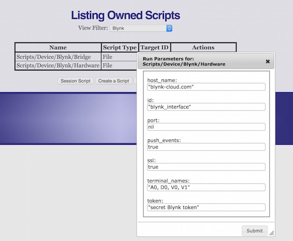
Testing Things OutOnce you have the Blynk application running on your smartphone and Virtual Wiring running the Blynk Hardware Device, there are some easy tests you can do. First, go to the Virtual Wiring Device Explorer page. You'll see a Device with the ID you created (ours was Now try the other direction. If you have a LED or display widget in your Blynk application, we'll try assigning it a value. Start by clicking on the Terminal within the Device Explorer page that corresponds to a Blynk display or light widget. While watching the Blynk application on your smartphone, assign an "on" value (unquoted) to your Terminal. If nothing seems to happen, try a number value. See how that works? Values assigned to Blynk Hardware Device Terminals show up on the corresponding widget within the Blynk application! Wiring Things UpNow that we have a Blynk Hardware Device working with the Blynk application, we can connect whatever we wish to Blynk by Wiring Virtual Wiring Devices to the Blynk Hardware Device. Want to monitor a value in the Virtual Wiring System with Blynk? Draw a wire from the appropriate Terminal in your Virtual Wiring system to a Blynk display widget's Terminal on your Blynk Hardware Device. Want to control something in the Virtual Wiring System? Draw a wire from a Blynk actuator widget's Terminal (a switch, a button, ...) to whatever Virtual Wiring Device Terminal you want to control! An ExampleIf you want to see a working example of a Virtual Wiring system using Blynk, checkout our Blynk Home Automation project. Blynk Device DescriptionsWe've already talked a bit about the Blynk Hardware Device. Here is a complete description of all the Blynk Devices supported by the Virtual Wiring system. Hardware Device
The Blynk Hardware Device creates a Virtual Wiring Device which notifies the Blynk server (and smartphone application) of changes in a Virtual Wiring system. It also notifies the Virtual Wiring application of changes made by the Blynk application. By default, the Hardware Device has no terminals - all its terminals are defined by the user. Blynk Hardware Devices are created by running the Hardware Script. The parameters for the Hardware Script are:
The following parameters are optional - leaving them alone generally works and is advisable.
Running the Hardware Script with the parameters listed below creates a Blynk Hardware Device.
The Blynk Hardware Device will have the ID "blynk" and "A0", "D0", and "V0" terminals. Whenever an event occurs at one the the Hardware Device's terminals, it will push the event to the Blynk server. Bridge Device
The Blynk Bridge Device allows Virtual Wiring to control Blynk devices using a Blynk bridge. The Blynk devices are native Blynk devices running code supplied by Blynk or written to conform with the Blynk application interface. A Blynk Bridge Device can be used to control another Virtual Wiring system's Blynk Hardware Device. If you have two Virtual Wiring systems running on two isolated networks, you may be able to connect them using Blynk Bridge Devices. By default the Bridge Device has no terminals - all its terminals are defined by the user. Blynk Bridge Devices are created by running the Bridge Script. The parameters for the Bridge Script are:
The following parameters are optional - leaving them alone generally works and is advisable.
Running the Bridge Script with the parameters listed below creates a Blynk Bridge Device.
The Blynk Bridge Device will have the ID "blynk_bridge" and "A0", "D0", and "V0" terminals. Whenever an event occurs at one the Bridge Device's terminals, it will use the V31 channel of Virtual Wiring's Blynk Hardware Device to push the event to the Blynk server, notifying the bridged Blynk device of the changes. Other values on the bridged device's terminals will not be shown on the Bridge Device terminals, since poll_interval is set to its default (nil) value. |
Catalina Computing, LLC.Copyright © Catalina Computing, LLC. (2013-2018) 
|
Page last updated: Fri Dec 23 03:01:39 2016 (UTC) |

