|
|
Projects << HomeAutomationProject | Software Overview | Sitemap | Downloads | Developers | Forums |
|
|
Home Automation ProjectThis project builds a standalone, distributed home automation system using 3 Raspberry Pi computers and 4 Ruggeduinos. Ruggeduinos are a version of the Arduino Uno with additional circuit protection. This project was featured in the 2014 July/August, edition #5 of Raspberry Pi Geek magazine. Everything you need to know for building this system is described in the Pi article and in this project. If you don't have a Raspberry Pi Geek #5 handy, here is a link to the article. You'll find a complete set of schematics, photos and scripts on this project page. The Script files in this project have been modified to run device-free on the Virtual Wiring system. You can run this project without additional hardware (no Ruggeduinos, no physical wiring). To bring up a system, all you have to do is run a Script. You'll find there's still quite a bit of functionality even without real hardware. If you want to build a real system, we'll show you our modifications, so you can restore the Scripts to their fully functional state. Many of the details of this project are in the Raspberry Pi Geek article, so we will only touch on them here. For additional information, read the "Home Automation" article in issue #5 of Raspberry Pi Geek. OverviewThis system runs and monitors about 50 different home devices - lights, pumps, alarms, heating systems, cooling systems. Often, it uses timers for determining turn on times and delays. The system sends and receives email and text messages as part of its monitoring and control. The home automation system is completely controlled by 3 Raspberry Pi computers and 4 Ruggeduinos. Two of the Pis and three of the Ruggeduinos are in the same box. The third Raspberry Pi and forth Ruggeduino is in a second box. We had separate boxes, because we wanted our systems to be near what they are controlling and monitoring. On each Raspberry Pi, we attached a PiGlow device for displaying CPU usage (and because they looked pretty cool). Each Pi has its own Ruggeduino(s) for connecting to all the physical wiring. Each Ruggeduino is mounted on an Aussie Shield, and all the wiring to the Ruggeduinos is done using the terminal blocks on the shields. The Aussies allow us to swap Ruggeduinos in and out without disturbing the physical wiring. Notice that all the more fragile components in the system (Pis and Ruggeduinos) can be swapped out in a few seconds. 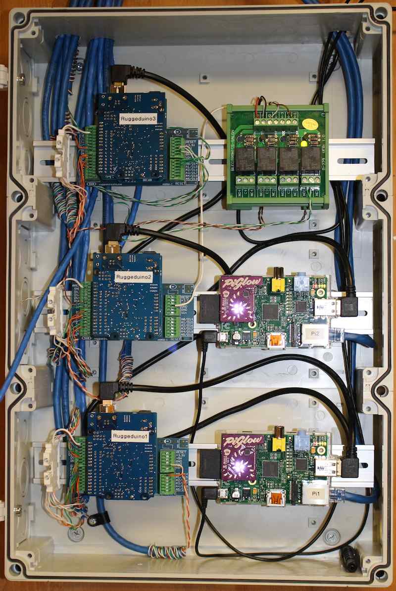
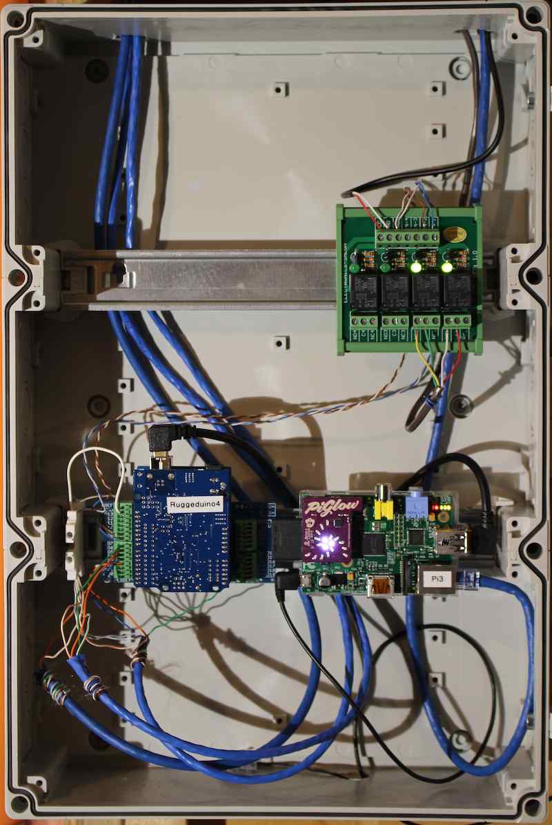
Pis are connected to Ruggedunios using a USB connection. Pi 1 connectes to Ruggeduinos 1 and 2, Pi 2 connects to Ruggeduino 3, and Pi 3 connects to Ruggeduino 4. Each Pi has an Ethernet connection to a common local network. SchematicsThese are the schematics for the home automation system. If you are running the software only version of the system, you won't need schematics, though they will help you understand how the system operates. Each Pi controls its own Ruggediuno(s) and physical devices. Pis also control Virtual Wiring Devices. The schematics show how all the Pis, Ruggeduinos, physical devices, and Virtual Wiring Devices are wired together. In each schematic page, there's a large dark box with smaller boxes inside it. Everything in the dark box supports a particular Ruggeduino device. In the lower left corner of the dark box, it says which Pi and Ruggeduino the box is for. The boxes inside the dark boxes are Virtual Wiring Devices and the wires between these are Virtual Wires. On the left and right sides of the pages, there are medium sized green boxes; these are physical devices. All physical wires run between these physical devices and Ruggeduino pins. The wires come in twisted pairs, with a solid color wire carrying a signal and a striped wire carrying a ground. Between the green boxes and dark boxes, there are small colored boxes. These describe the physical wiring. The small box colors tell us the color wires we are using. Boxes with a colored border and white interior are striped wires. Single color boxes are solid color wires. Boxes containing "D" and "A" letters go to a pin on a Ruggeduino. A solid orange box with "D10" lettering means connect an orange wire to Ruggeduino pin D10. A box with an orange boarder and "0V" inside means an orange and white striped wire connected to Ruggeduino ground. In some of the schematics, you will see pull-up resistors. We mounted ours on Arduino Proto Shields and sandwiched the Proto Shields between the Ruggeduinos and the Aussie Shields. 


ScriptsVirtual Wiring Scripts build the 3 Pi systems you see in the schematics. If you haven't already, you need to install the Virtual Wiring System on a host computer. Any *nix computer will work as a host - you don't need a Raspberry Pi. Download the zip file containing all the Scripts by going to the project download page and clicking on the Scripts link. Place the zip file in your Start up (or restart) your Virtual Wiring application application, so your home_automation Scripts are loaded into the Virtual Wiring application's Script cache. Go to the Scripts page, click on the View Filter, and select "home_automation". Click on the "Run" action of the "startup_pi1.script", "startup_pi2.script", or "startup_pi3.script" to run either the Pi 1, 2, or 3 system. Go to the Device Explorer page and start poking around your system. Look at the values on the terminals in the system. Try changing values and see what happens. Look at the Wires page. These are all the virtual wires in the system. Try adding and deleting wires and see how the system reacts. Open Scripts in the Script Viewer - you can see State Machine tables, how Devices are configured and wired, and there are lots of informative comments. Because this system isn't talking to real hardware, you can't hurt anything by playing with it. If you get into trouble, restart the system and rerun a startup Script. Running 3 Systems at OnceIf you've looked at the Console Log page, you may have noticed your system is logging error messages. These won't keep your system from running, but they are telling you that your system is trying to talk to another Virtual Wiring system and failing. The original home automation system runs on 3 Rasperry Pis, all talking to each other. The Pis have Terminals Sharing Devices which let them create Virtual Wiring connections between the 3 systems. They are sharing common signals, and they are passing heartbeat information so they can detect when another system has gone down. You can recreate all 3 systems on your host system. The Scripts have been modified so their Terminals Sharing Devices are running on localhost:4567, localhost:4568, and localhost:4569. If you run your Pi 1 system on port 4567, your Pi 2 system on port 4568, and your Pi 3 system on port 4569, your 3 systems will all be able to talk to each other. To run 3 systems at once, you will need to run the Virtual Wiring application 3 times. We'll run it 3 times all on the same host. When you started your Virtual Wiring system, you ran a script called "run_vw_application.rb". It ran the virtual wiring application on port 4567. This script takes an optional parameter, so you can run the application on any port. After running "run_vw_application.rb" the first time, leave it running and open a new terminal session. In your new terminal, navigate to your Virtual Wiring application directory and type:
Now you are running another instance of the Virtual Wiring application on port 4568. Open a third terminal session, navigate to the Virtual Wiring application directory and type:
Now you have 3 instances of the Virtual Wiring application all running on the same machine. If you run each of the 3 Pi startup Scripts for each of the 3 instances, your 3 systems will all be talking to each other. Starting up the 3 Pi SystemsNow that we have 3 instances of Virtual Wiring running, we are going to run one of the 3 Pi systems on each of them. Go to your browser and display the Virtual Wiring application running on port 4567. If you are running the browser on the same machine you are running the Virtual Wiring application, the address will be "http://localhost:4567". Next, go to the Scripts page and run the Script "startup_pi1.script". Your Pi 1 system is up and running. Go to your browser and display the Virtual Wiring application running on port 4568. If you are running the browser on the same machine you are running the Virtual Wiring application, the address will be "http://localhost:4568". Next, go to the Scripts page and run the Script "startup_pi2.script". Your Pi 2 system is up and running. Go to your browser and display the Virtual Wiring application running on port 4569. If you are running the browser on the same machine you are running the Virtual Wiring application, the address will be "http://localhost:4569". Next, go to the Scripts page and run the Script "startup_pi3.script". Your Pi 3 system is up and running. That does it. You now have 3 Pi systems running concurrently and communicating using Terminals Sharing Devices. In your browser, you can switch between them by modifying the port number in the http address. Testing Things OutNow that you have all three Pi systems running, you will no longer receive error messages in the Console Log. Navigate to the Console Log for any one of your 3 systems and check it to see if you are still receiving error messages. Each of your Pi systems monitors the other 2 to see if they are running. If any one of your 3 systems goes down, the remaining systems will send out a message. You can check this by killing one of your 3 systems, and navigating to the Device Explorer page and looking at the "email_messages_pi" Device on either of the two remaining systems. Whatever is displayed next to the "message" terminal gets sent as an email or text message (though for this test system, actual sending is disabled). To test monitoring, go to your Pi 3 terminal session running on port 4569. Kill the application by holding down the control key and hitting the "c" key. Go to your browser and navigate to Pi 1's home page (perhaps "http://localhost:4567"). Click on the "email_messages_pi1" Device and look at the "message" terminal. It probably says: "Pi1 house control system rebooted". Wait 20-30 minutes and refresh your screen. Did the message change? If you don't feel like killing your Pi 3 system, or your don't feel like waiting 20 minutes, you can force an error. In your Pi 1 system's Device Explorer page, open the "heartbeat_timer_pi2_pi1" Device and change its "out" terminal value from 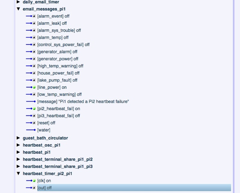
You can use Device Explorer to experiment with your system and better see how it works. Fully Enabling the SystemTo allow this system to run without physical devices, we altered some of the Scripts. To learn how to restore your Scripts to their fully functional state, click here. |
Catalina Computing, LLC.Copyright © Catalina Computing, LLC. (2013-2018) 
|
Page last updated: Thu Feb 19 17:32:33 2015 (UTC) |