|
|
Projects << BlynkHomeAutomationProject | Software Overview | Sitemap | Downloads | Developers | Forums |
|
|
Projects << BlynkHomeAutomationProject | Software Overview | Sitemap | Downloads | Developers | Forums |
|
|
Blynk Home Automation Project - OverviewFor this project, we are building a system demonstrating many of the components useful in a home automation system. This system will control light bulbs and appliances either by remote control or automatically (using timers, state machines, etc.). In addition, it will demonstrate a switchable outlet which works anywhere with Internet access in the world, and it will include a home monitoring alarm system and camera. The entire system is controlled and monitored from a smartphone (running the Blynk application). This project can be built in a few hours and requires no programming. 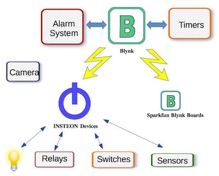
Once one understands how to build this system, it's straightforward to change and augment it with additional components (switches, sensors, etc.) and functionality. Contents
Hardware ComponentsWe'll build this system out of standard components, so you can find them easily on the web or in stores. We'll be using some free software (free for home projects and other non-profit making activities) called Virtual Wiring. Virtual Wiring will run on any *nix host. We'll use a Raspberry Pi 3 for this project, but we've run Virtual Wiring on Raspberry Pi 1s, 2s, C.H.I.P. computers, Beagle Bones, Mac computers, and many others. The Virtual Wiring system supports a variety of hardware devices (Blynk devices, XBee devices, Z-Wave Devices, Arduinos, to name a few), and if you can do some Ruby programming, you can add your own devices. For our system, we'll use a number of Virtual Devices (devices which function without any hardware requirements), INSTEON devices, a Sparkfun Blynk board, and an iPhone or Android phone. 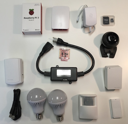
All but the INSTEON devices may be familiar to you. Why, you might ask, are we using INSTEON (as we've mentioned, Virtual Wiring supports many other device types). Instead of INSTEON, we could craft our own solutions using XBEEs, Arduinos, Blynk boards (and others). We are using INSTEON to save time (and it may be cheaper as well), and because the INSTEON technology provides all the devices we need (which again saves time, because you only need to set up one type of thing). If you like, you can substitute other devices for the INSTEON ones, but you'll set your project up more quickly if you use the ready-to-go INSTEON solutions we have. Here's the list of hardware components:
System DescriptionOur system will contain an alarm system, a timer controlled light bulb, a remote controlled light bulb, a remote controlled appliance outlet, and a remote controlled appliance outlet which works anywhere there is internet (an ultra long distance switch). A Blynk interface will control and monitor the alarm, the light bulbs, and the long distance appliance outlet. 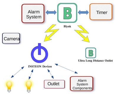
The Alarm SystemThe alarm system detects motion and sends out emails and text messaging alerts. The alarm system is turned on and off using emails, text messages, or the Blynk user interface. When the alarm system is off, it sends no alerts. When it is on, it sends alerts. We also have a wireless wall switch (which you can place most anywhere in your house), so you can turn the alarm system off and on when you walk in and out of the door. Any time the alarm system is turned on or off, it sends messages (email and/or text) so you'll know your command is successful and your system is secure (even if a bad guy knows how to turn your system off, you'll know about it). 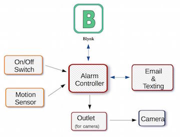
The CameraRunning in parallel with your alarm system, there is a security camera. When you get an alert, you can go to your cell phone and see what's going on. For the camera, you can use any remote video camera (these are widely available on the internet and in department stores). However, we add a small wrinkle to the camera system for personal security. Some of us find the idea of having a live camera around when we're home a little creepy. Sure, your camera supplier will tell you your camera is secure, but there's no guarantee a hacker can't be watching you over the internet. We fix this problem. Instead of plugging your camera straight into a wall outlet, we plug it into a remote control appliance outlet. We turn the outlet on when the alarm system is on (and you aren't there) and off when the system is off. So when your alarm system is disabled, your camera will be powered off, and there's no way a hacker can use it (and you'll be able to see the camera is off because it's power light will be off)! The Timer Controlled Light BulbWe'll create a light bulb which turns on and off at certain times of the day. Here we will make it turn on 20 minutes before sundown and off at 11:00PM. You can adjust the times to your liking as well as which days of the week and/or month. You can even turn the light bulb on and off multiple times per day. You'll be able to override the timer from your Blynk interface. The Remote Controlled Light BulbWe'll create a light bulb you can control from your Blynk interface. The light bulb will be dimmable, and it can be most anywhere in your house. You'll be able to control your light bulb from your cell phone (running Blynk). The Long Distance Appliance OutletWe'll create an outlet you can turn on and off from your Blynk interface. The outlet can be anywhere in the world there is Internet! You'll be able to control your worldly outlet from your cell phone (running Blynk). The Blynk InterfaceOur whole system will be controlled and monitored from the Blynk interface. Here's what it will have:
System Hardware Break DownThe AlarmThe alarm system requires a motion detector, a wall switch (for enabling and disabling the alarm), a camera, and a remote controlled outlet (for turning on and off the camera). For motion detection, we use an INSTEON Motion Sensor. It's a self contained battery powered device. You put it anywhere within range of your INSTEON system and you can detect motion. Just add a 9V battery and you're in business - easy. For the remote controlled outlet, we use an INSTEON On/Off Module. Plug it into a free outlet, and its outlet is a remote controlled power outlet. For the camera, there are tons of these. HD cameras (or better resolution) will give you a more detailed image. For ours, we bought a Samsung SmartCam Plus 1080p at Costco. For a wall switch, we use an INSTEON Mini Remote Switch. Like the motion sensor, it's a self contained battery powered device - you can stick it anywhere in range of your INSTEON system. It's got a single button which you can push up (to enable the system) or down (to turn off the system). The last alarm component isn't a hardware device you need to buy, but someone needs to provide you an email account you can send and receive messages to and from. It needs to be a dedicated account, because the alarm system will read and delete all messages it sees in the account; it will also send all its messages to this account. For our system, we created a standard Gmail account. Timer Controlled Light BulbTo make a timer controlled light, we need a remote control light bulb and a timer. For the light bulb, we use an INSTEON LED Light Bulb. These can be turned on and off (and dimmed as well). We'll just be turning the light bulb on and off, for now. For a timer, we'll use a Virtual Wiring timer. It's a software-only device which can turn anything in the Virtual Wiring system on or off at programmable times of the day; it can also turn things on and off relative to sundown and sunset (if you tell it your longitude and latitude). Like all software devices in the Virtual Wiring system, you can build as many of these as you want without spending a penny. Remote Controlled Light BulbFor a remote controlled light bulb, we'll use another INSTEON LED light bulb. We'll be able to turn this light bulb on and off and dim it. Long Distance OutletFor our long distance outlet, we'll need a device which can get onto the Internet and control a remote controllable outlet; we'll also need a remote controllable outlet. For our Internet device, we'll use a Sparkfun Blynk Board; for our remote controllable outlet, we'll use a PowerSwitch Tail (PowerSwitches are also available from Sparkfun). 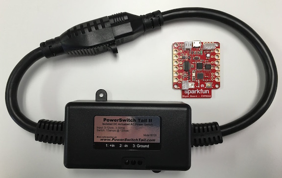
The Blynk Board comes with built-in software which talks to a Blynk server. For this project, we'll use the built-in software (no need to write your own). Later, if you want to add features, you can write your own Blynk Board software. GlueTo tie all our hardware components together, we are going to need some glue. Fortunately, our "glue" elements consist of easily wired or wireless components, so there is very little work involved with "gluing". ControllerOur first glue element is a controller. The controller runs our system and talks to the Blynk and email servers. For our controller, we are using a Raspberry Pi 3 (though a Pi 1 or 2 will work as well). The Pi needs to be connected to the Internet via Ethernet or WiFi (WiFi is built into Pi 3s!). 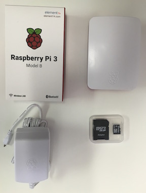
If you don't have a Pi available, feel free to substitute another *nix based system. We've used all kinds of computers - Plug Computers, Beagle Bones, C.H.I.P.s, even Mac Computers. Just be sure your computer has a way to connect to the Internet, a spare USB port, and a decent amount of RAM (generally, systems should have at least 256M of memory). INSTEON ModemINSTEON components are wired and wirelessly controlled devices. To control them, we need an INSTEON Modem. The modem sends and receives both wired (over power lines) and wireless signals to and from INSTEON devices. Battery operated devices, like the wall switch and motion detector, communicate wirelessly. Switchable outlets, like the On/Off Module, and light bulbs use both wireless signals and power line signalling. We use an INSTEON 2413U PowerLinc Modem. The Modem plugs into an AC outlet and plugs into your controller's USB port using a standard USB AB cable. 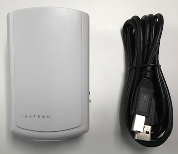
Building the SystemHopefully, we've given you a good grasp of what this system will do. Now, it's time to build it. We'll cover it a piece at a time. ControllerFirst, we need to set up the Virtual Wiring software on your controller (this is your *nix computer). It should be running and connected to the Internet. To install Virtual Wiring, Go to the http://www.catalinacomputing.com website and follow the HowTo for installing Virtual Wiring on a Raspberry Pi. When you download the software, you'll want to download the most recent version (we generally keep the 2 most recent releases on the site). The software is named "vw_application_yyyymmdd.zip", where "yyyy" is the year it was released, "mm" the month, and "dd" the day, so use the name to determine the most recent software. The INSTEON ComponentsNow we will install all the INSTEON components in the system. First we will do some INSTEON configuration, and then we will install all the components into the Virtual Wiring system. 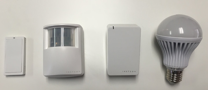
INSTEON ConfigurationTo create an INSTEON system, we have to introduce all the pieces to one another. The introduction tells the devices who they are allowed to talk to (by default, they won't talk to devices they don't know). In INSTEON terminology, this is called creating "links", where a link is a uni-directional path that allows one device to send messages to another. Another way of thinking about a link is it's a one-way network connection between 2 devices. For our INSTEON system we are going to create the links. Again, using INSTEON terminology, a link starts at a "controller" and ends at a "responder" (note that a responder responds by doing what the controller tells it to do, not by telling the controller what it's doing). So here is a list of the links we are going to create: Hopefully, the list of links makes sense. Our Modem is our control center, so every device either sends status to the Modem or receives commands from the Modem. The Mini Remote Switch and the Motion Sensor send data to the Modem, and the light bulbs receive commands from the Modem. The On/Off Module device is unique, because it receives on and off commands from the Modem, and it can also be turned on and off by a button on the side, so it can send status changes to the Modem. INSTEON links are easy to create. Each INSTEON device has a small button (on battery powered devices, it may be located inside with the battery). To create a link, get your devices within 10 feet of each other and press and hold the link button on the Controller until it beeps and starts blinking. Then press and hold the link button on the Responder until it beeps and the controller stops blinking - you've created a link. Plug in your modem and On/Off Module, put the batteries in the Motion Sensor, and charge up your Mini Remote Switch. Then create the 6 links listed above. Note that your light bulbs probably don't have a link button on them; if you leave them off until the time comes to press their link button, they'll complete the link when they power up. So just screw in / turn on your light bulbs when it's time to press their link button. See the INSTEON Devices page if you are interested in more information about linking. Note: while you are setting up your links, write down the 6 digit INSTEON address of each device. These look something like AB.10.CD, where each digit can be a number from 0-9 or a letter from A-F. Typically, they are located somewhere on the outside of the INSTEON device (though it may be inside with the battery for a battery powered device). These will come in handy in the next section. Add the INSTEON Devices into Virtual WiringBefore adding our INSTEON devices, we're going to give a little introduction to the Virtual Wiring Software. In nutshell, it turns your controller into a web server at port 4567 (http://localhost:4567, if you are running your browser on your controller). The server has 4 separate pages: The Home page for viewing and changing the state of the system, The Scripts page for adding devices to the system, the Wires page for connecting devices together, and the Console page for lower level operations and debug. You can see links to the 4 pages at the top of your Virtual Wiring web page. To add any devices to the system, go to the Scripts page. There, there are Scripts (no surprise) which we can click on to add devices to the system. Here, we want to add INSTEON devices, so go the the Scripts page, click on the "View Filter" button at the top of the page, and select INSTEON. We now have a list of possible INSTEON devices we can add to the system. 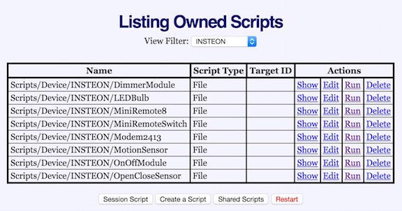
The first device we want to add is the Modem2413 Device. Find the Modem2413 in the Scripts list, and click on its "Run" action. You'll see a dialog box with the fields: "id", and "port_location". For the ID, we'll give it a name that makes sense, "modem" (and use quotes). The port_location is how your controller identifies the modem. Plug your Modem into your controller's USB port using the cable included with your Modem. Open a *nix command window on your controller, and type "ls -lrt /dev". This command will show you all the devices your controller knows about with the recently added ones at the bottom of the list. You should see something like "/dev/ttyUSB0" (on a Raspberry Pi) near the bottom of the list. If you don't or you aren't sure of the name, unplug the Modem's USB cable and run "ls -lrt /dev" again and see which device disappears. That's the port_location we are looking for. So for the fields in your dialog box, you should have something like (both in quotes): Click on the "Submit" button and you should should get a message saying that your Script ran correctly. If you go to your Console page and click on the "View Log" button at the bottom, you'll see a log with lines at the bottom which look something like this (your times and INSTEON device addresses will be different): Make sense? Perhaps a bit of sense? Those IDs are the INSTEON address of the Modem and the INSTEON addresses of the 5 devices we linked to previously. Now we need to add the remaining 5 devices (On/Off Module, 2 light bulbs, the Motion Sensor, and the Mini Remote Switch) to our system. Find their Scripts on the INSTEON Scripts page and run each of them. Each Script will ask you for an "address", an "id", and a "port_location". The address is the INSTEON address you wrote down from the previous step. The "id" is the name we will give our device, and the port_location will be set to OnOffModule: LEDBulb: LEDBulb: MotionSensor: MiniRemoteSwitch: After running the Scripts, go to the Home page of your system and take a look at your "devices". You should see your names there and you may even see some values for your sensors and lights! Click on the camera_power Device's "1" terminal. In the dialog box that shows up, type either 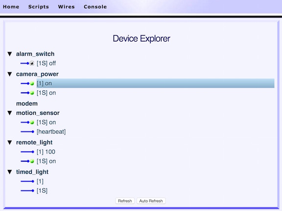
Now we are going to do something to save our work - we wouldn't want to do this configuration every time we powered up the system. But first, a little background information. The way the system works, every time you run a Script successfully, it saves what it did into a Session Script. To see it, go to the Scripts page and click on the "Session Script" button at the bottom. You'll see a Script which recreates the system we've built so far. 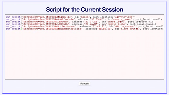
Copy the entire Session Script and go back to the Scripts page. Select "user" in the "View Filter" and then click on the "Create a Script" button at the bottom of the page. Type in The Blynk InterfaceWe are going to add the Blynk Interface to the system. The interface is what you'll see on your cell phone that monitors and controls the system. Before creating and adding our interface, we need to create a new Blynk project. If you haven't already, install the Blynk app on your cell phone by going to your phone's App Store. Start up the Blynk app and create a new project called "My Home" (or a name of your choosing) of type "Generic Board". Mail your new project's authorization token to yourself (we will be using it shortly). Next, we are going to create our interface. We won't go into the details of how to create interface elements with Blynk (it's covered in the Blynk documentation, and most of it is pretty intuitive), but we will describe which widgets we use and how we configure them. As we stated above, we want our interface to:
Below is a table outlining the Blynk widgets we create for our interface screen. Use it to create your own interface. 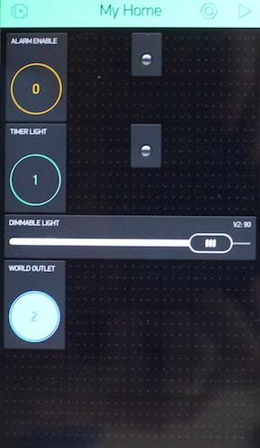
Once we've created our interface and have our authorization token, we are going to create a Virtual Wiring Device which connects to our interface - it acts like a Blynk hardware device, and it interacts with the Virtual Wiring environment. It's called the Blynk Hardware Device. For more information on Virtual Wiring Blynk Devices, see our Blynk Devices page. Go to the Scripts page and select "Blynk" in the View Filter. From the list of Scripts, run the Hardware Script. You'll get a dialog box. In the "id" field, type Blynk Hardware Device values: Take a look at your Home page again and click on your new "blynk_app" Device. See the terminals we created? Now run the Blynk app on your smart phone and push your buttons and slide the slider. Click on Refresh at the bottom of the Virtual Wiring Home page. See what is going on? The Virtual Wiring Device and your Blynk app are mirroring each other! From the Home page, click on the bynk_app Device's V0 and V1 terminals and assign the value 255 (unquoted) to each of them. See the LEDs on your phone's Blynk app light up! 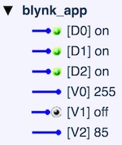
The Long Distance OutletWe use a Sparkfun Blynk Board and a PowerSwitch Tail (both available from sparkfun.com) to make an almost-anywhere remote control outlet. We use an output pin on the Blynk board to turn the PowerSwitch Tail on and off; specifically, the Blynk Board's D5 output goes to the PowerSwitch's 1 (+in) input, and the Blynk Board's Ground goes to the PowerSwitch's 2 (-in) input. Since the PowerSwitch is a normally closed device, it will be on by default and off (open) when the Blynk Board's D5 output is on. Set Up the Sparkfun Blynk BoardFollow the Sparkfun Blynk board installation instructions. When you are done, you should have a Zebra on your smart phone that controls your Blynk Board's color LED. Mail your Blynk Board's authorization token to yourself - you'll need it shortly. Next we are going to create a "bridge" from your "blynk_app" Device to your Blynk Board's D5 output. A bridge is a Blynk term for a technique for modifying one Blynk hardware device from another. We are going to create a bridge from our "blynk_app" device to the Blynk Board. Go to the Scripts page and select "Blynk" in the View Filter. From the list of Scripts, run the "Bridge" Script. You'll get a dialog box. In the "channel" field, type Blynk Brige Device values: Try using the Virtual Wiring Home page to poke Note: make sure you have your Blynk Interface up and running when you set up your Bridge (the blynk_app Device). It needs this device to form the near side of the bridge (the place we bridge from). AssemblyFind 2 22-24 gauge solid copper wires about 3 inches long. Strip 1/4 inch of insulation off of one end of each wire and 1/2 inch off the other end. Screw the short end of one wire into the PowerSwitch's 1 terminal and twist the long end onto the Blynk Board'd D5 terminal. Attach the other wire (similarly) between the PowerSwitch's 2 terminal and the Blynk Board's Ground terminal. Secure the Board to the PowerSwitch with 2 rubber bands. 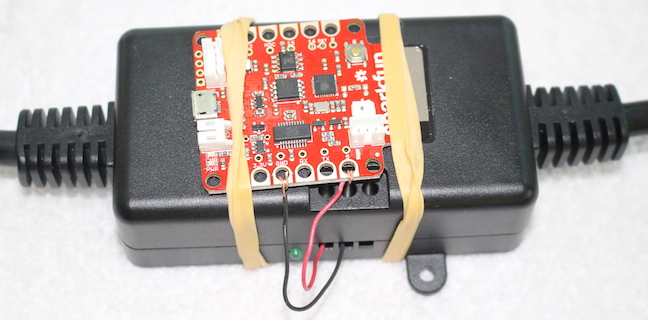
Note that this is a pretty primitive (and not terribly reliable) way of making our outlet. It's good for demonstration purposes, but you may want to solder your wires to the Blynk Board and put it into a protective enclosure. The CameraWe use a camera to check up on our home when we receive alarm messages. Feel free to buy whatever remote camera you like. Just make sure it allows remote viewing from your cell phone (having to be within WiFi range of your camera wouldn't be useful). Higher resolution cameras give a better view, but they are more expensive. Having a camera with night vision is probably required, because you'll want to use it at night when the lights may be off. As we said earlier, we bought a Samsung SmartCam Plus 1080p at Costco, and it works well. 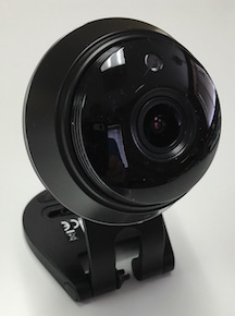
Once you've got your camera set up with your phone, plug it into the INSTEON On/Off module. Now the alarm system can turn the camera on and off and keep hackers from spying on you. The Virtual Wiring EmailerOur alarm system uses email and text messages to send alerts. It also allows you to send it text and email messages for status information and to turn it on and off. To make this all work we'll use a Virtual Wiring Email Device. The emailer requires a dedicated email account on an email server to function. Set up an account at your favorite provider and remember your user name and password. For our system, we created our account on Gmail. If you choose to create an account on Gmail, there's one small extra step you'll need to perform. Gmail has extra protection against less secure applications (such as this one), so you'll need to turn it off. Go to https://www.google.com/settings/security/lesssecureapps, login with your new user name and password, and turn on access for less secure apps. To create an email Device, go to the Scripts page and select EMail in the View Filter. Run the TextMessagingPOP Script. Fill out the dialog box as shown below and submit it. You'll need to use your personal email_address (cell phone's messaging address), email account password, and email account user_name. Not everyone knows their cell phone's messaging address. Carriers have their own way of encoding these, but typically, they involve the phone number and the carrier's email server. A Verizon smart phone with number 1235551212 would have a messaging address of 1235551212@vzwpix.com. For other examples, see here. You can also send to plain old email addresses as well. You can send to multiple email addresses (and text meessaging devices) at once by using the EMail addEmailAddress Script. The Virtual Wiring Virtual DevicesWe've got a handful of smaller Virtual Wiring Virtual Devices we need to add. These are software only devices which perform lots of interesting functions. Well be using some of them here. To get started, go to the Scripts page and select "Virtual" in the View Filter. The Alarm DeviceWe'll add an Alarm Device to monitor our motion detector and respond to commands to the alarm system. Run the Alarm Script with the "id" parameter set to "alarm". Next run the "Alarm/InputTypes/Equal" Script with the following parameters: This Script will create a "motion" terminal on the Alarm Device which triggers the alarm when the terminal is on. Finally go to the Console and run the command: This will cause the Alarm Device to only send certain kinds of text messages. Alarm Device State MachineState Machines let us define customized Devices using a State Machine specific language. Here we will define a State Machine which filters out Alarm messages, unless the Alarm is enabled (that way we will only get messages when the alarm is enabled). Here is the State Machine: Go to the Scripts page, set the View Filter to "user", and click on the "Create a Script" button. For the name use: Edit the alarm_filter.yaml Script and copy the State Machine code above into it. Save the Script. Now we will create the State Machine. Go to the Scripts page and set the View Filter back to Virtual. Run the (top level) StateMachine Script with the following parameters: LED MappersOur Blynk status LEDs for the alarm and timer lights require on values of 255 (for fully on). Right now what would be feeding them (the alarm enabled signal and the timed light status signals) is just Go to the Scripts page and select Virtual in the View Filter. Run the Mapper Script with one and then the other of the following 2 sets of parameters: And: The TimerWe need a timer to turn our light on 20 minutes before sundown and off at 11:00PM. To make your timer work properly, make sure you controller has the right time (and time zone configured). We'll use a Sun Interval Timer Device. Go to the Scripts page and select Virtual in the View Filter. Run the TimerSunInterval Device. Fill out the dialog box as follows (leave other parameter values unchanged): Notice for the timer, we have to give it a latitude and longitude - that's so it can calculate when sunrise and sunset are. Here we give it the location of New York City in the US. You'll probably have a different location. Note: write southern latitudes and western longitudes as negative numbers. An InverterAs we mentioned earlier, our PowerSwitch Tail device is normally closed. That means if we give it an "on" signal, it will turn off (and visa-versa). Since we want our Tail to be controlled by a button (in our user interface) which turns it on when the button is on, we are going to have to invert the button signal (inverters turn ons into offs and offs into ons). So we'll make an inverter. Go the the Scripts page and select Logic in the View Filter. Run the Inverter Script with the id parameter set to "outlet_inverter" (leave the other parameters the same). Wiring Things TogetherNow that we've built all the Devices we will need, it's time to connect them all together. We use something called Virtual Wires (hence the name Virtual Wiring), which is a lot like using real wires except you create them using a web screen. Let's get started. First go to the Wires page. There you'll see two terminal blocks. You create wires by dragging them from terminals on the left terminal block to terminals on the right one (if this doesn't work for you the first time, try dragging from a little to the left of center-terminal). You can delete a wire by clicking on it. Instead, if you prefer, you can view, add, and delete wires by using a table driven methodology (just click the "Table View" button at the bottom of the page). The view with terminal blocks (the Punchblock View) and the Table View are functionally identical. (You can also create wires by just typing them into the Console, but we won't be doing that.) Generally, for smaller designs like this one, the Punchblock View is preferable. For larger designs, the Table view is preferable. For our first set of wires, let's work on the primary device of the alarm system - the alarm Device. The alarm Device's "command" input will get commands from our alarm_mailer's "output". It will also get on and off commands from our alarm_switch. So let's draw those 2 wires. 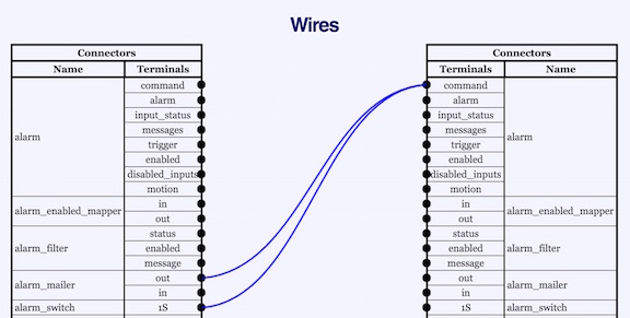
Now lets add the other wires for our alarm system. We'll lay them out in table form here, so you can draw them. Terminals will be named by their Device name followed by their terminal name. So the alarm command terminal would be called alarm:command. Here are the rest of the wires for our alarm system. Now let's connect up our Blynk Interface. And lastly, wire our timer to the timed_light. Our Final Script and Some Screen ShotsHere is our final Script. To make it easier to read, we've added comments (lines that begin with a "#") and additional spacing between lines. Now is a good time to back up your completed system by going to the Session Script page and copying your completed project Script to your home_automation.script Script file. You may want to add comments and spacing to your Script so it looks more like our final Script and is easier to read. Here are Screen Shots of the Home page and Wires page for the complete system. Testing Things OutAfter completing your wiring, let's test things out. Make sure all your devices are powered. Make sure Virtual Wiring is running and visible in front of you. Go to the Virtual Wiring Home page and click on "Auto Refresh" at the bottom of the page - this will make the page self refresh every 3 seconds or so (so you don't have to refresh it manually). Grab your smart phone and run the Blynk Application. Enable and Disable the AlarmWith your Home page in front of you, press the Alarm Enable button in the Blynk Application. Try it a couple of times (waiting up to a few seconds to see your results). You should see the enabled terminal on your alarm Device turn on and off, and your camera's power should turn on and off (the INSTEON On/Off Module may make an audible click, and it's power light will change between green and red). The Enabled LED on your phone's Blynk screen will also turn on and off. You should be getting messages telling you your alarm is enabled and not enabled. Everything OK? Great! Problems? Check the Virtual Wiring Log for clues. Check your wiring. Check your Motion DetectorTurn your alarm on (enable it using Blynk). Wait 30 seconds, move in front of the motion sensor. Look at your alarm_mailer Device on your Home page. Is there an alarm message on its "in" terminal. You should be getting that message shortly (though these usually happen within a few seconds, they can take longer, depending on how your cell phone company is feeling). Turn the alarm system off by responding to your alarm's emails/text messages with the single email/text message Check your Alarm Enable SwitchTurn your INSTEON Mini Remote Switch on and off. Your alarm system should be enabled and disabled (and you'll get messages telling you so). Check your Timed LightFrom your Blynk screen, press the Timer Light button. Your light should turn off and on, and the Blynk LED should do the same. Note that the Blynk LEDs are getting actual feedback from the light, so when they turn on and off, your light bulb is telling them to do it (a nice handshake). We can't test your timer, but if you leave your light off and check it 20 minutes before sunset, it should turn on. If it is already past sunset (and before 11:00PM), leave the light on and check that it turns off at 11:00. Check your Dimmable LightUsing the Blynk app, slide the Dimmable Light slider back and forth. Your INSTEON light bulb should dim and brighten. Check your World OutletUsing the Blynk app, press the World Outlet button. Wait (up to a few seconds). You should hear a loud click from your PowerSwitch Tail, and the Tail's and Blynk Board's LEDs should change state. Check that when Blynk says on, the Tail is on (remember, the default setup for the Tail is to turn off when its LED is on). Wrap UpWe hope you your are enjoying your new Home Automation system. If you want to expand it by adding more lights, more motion sensors, additional wireless switches, more controls on your Blynk screen, we hope we've shown you enough so it's easy to do that. If there's something here we haven't covered (we've only scratched the surface of supported Virtual Wiring devices) our www.catalinacomputing.com website has lots more information. Have fun! TipsUndoing Changes to the Virtual Wiring SystemWant to undo something you've already added to the Virtual Wiring system? Save your current work minus the part you don't want to keep from the Session Script and click the Restart button at the bottom of the Scripts page. Then run your saved Script. Restarting your system will clean out all your Devices; running your saved Script will restore only the parts you've saved (and wanted). Extending INSTEON Range, Power BridgingINSTEON devices communicate by using wireless signals and your home's AC wiring. All AC powered INSTEON devices (e.g. your Modem, light bulbs, and your Off/On Module) act as repeaters and wireless hubs, further extending the INSTEON range. However, when your devices are far apart, the communication breaks down - devices fail to work or fail to work reliably. We've found that INSTEON wireless devices work a few 10s of feet from the nearest AC device when there's a clear line of site, and perhaps only about 10 feet when a there's a person standing in front of them (which is often the case when we are pushing our alarm enable switch). INSTEON range can be extended by adding additional INSTEON AC devices. INSTEON makes a Range Extender for just this purpose (though you may want to just buy On/Off Modules instead, since they also function as extenders and have the added benefit of being able to switch devices). If one of your INSTEON wireless devices isn't functioning properly, try plugging an extender into a nearby outlet. If you are still having problems (perhaps even problems between INSTEON AC devices), you may need to "bridge" between the 2 halves of your AC system (most house power systems actually have 2 separate AC circuits that come in from the street). Two INSTEON AC devices on separate halves of your AC will automatically form the bridge you need, if they are in range of each other, so you can just try adding extenders and see if that fixes the problem. If you want to be more precise, there are INSTEON tests you can run to learn what's on what half (you'll need to look at the instructions that came with your INSTEON devices and/or Google around). To get you started, try pressing the link button on your INSTEON Modem 4x quickly (as we found by reading our INSTEON PowerLinc Modem's Quick Start Guide). Getting Your System to Start Up AutomaticallySee our FAQs page. Fun Things to TryOscillatorsThere's a neat Virtual Wiring device called an Oscillator. Try adding one to your system, setting its period to 10 (seconds). This will make an on/off signal which changes state every 5 seconds. Try wiring it to your light bulbs and other actuators in your system - watch them turn off and on! |
Catalina Computing, LLC.Copyright © Catalina Computing, LLC. (2013-2018) 
|
Page last updated: Fri Dec 23 03:40:17 2016 (UTC) |