|
|
Devices << ArduinoDevice << ArduinoDevices << AdafruitDevices | Software Overview | Sitemap | Downloads | Developers | Forums |
|
|
Devices << ArduinoDevice << ArduinoDevices << AdafruitDevices | Software Overview | Sitemap | Downloads | Developers | Forums |
|
|
Adafruit Devices on ArduinosHere we describe the Adafruit devices we support. There are many devices on the Adafruit website (switches, relays, LEDs) which require only the standard pin configurations. To learn more about Adafruit and their devices, see http://www.adafruit.com. If you are interested in using an Adafruit device which is not in this list, you may be able to support it using standard pin configurations. The Adafruit devices we support explicitly are: Motor/Stepper/Servo Shield V2 Both these shields are useful for robotics projects. The Motor Shield can control a robot's drive unit, and the Servo Shield can position the robot arms, head, cameras, etc. The Adafruit Scripts are in the Arduino/Devices Scripts directory in the Adafruit subdirectory. The Motor/Stepper/Servo Shield V2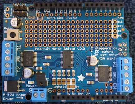
The Adafruit Motor/Stepper/Servo Shield is a small board which plugs onto an Arduino (an Arduino shield). The shield controls up to 4 motors and an additional 4 individual pulse width modulators (PWMs). The 4 sets of motor controller outputs can drive high currents. Each set of motor controller outputs is controlled by 3 dedicated PWMs. One of the 3 controls the motor speed, and the other 2 control motor direction (see the Adafruit specification for details). Note: the Adafruit design supports both standard electric motors as well as stepper motors. Our Motor Shield Script supports standard electric motors, but not stepper motors. The Motor Shield uses the Arduino's I2C bus for configuration and control. The bus lets you set the overall PWM frequency for all the PWMs as well as the duty cycle of individual PWMs. Configuring the ShieldTo configure the Adafruit Motor Shield, run the MotorShieldV2 Script in the Adafruit subdirectory. The Script adds 16 input terminals to your Arduino Device. 12 of the terminals are for controlling 4 motors, and the remaining 4 control 4 dedicated PWMS. Each of the inputs takes a duty cycle value from 0-100, or the values "on" or "off" ("on" is the same as a duty cycle value of 100, and "off" is the same as a duty cycle value of 0). Each motor is controlled by a set of 3 motor terminals: the "pwm", "in1", and "in2" terminals. The "pwm" terminal is used to set the pwm value for a motor (the speed), and the "in1" and "in2" set the motor's direction ( in1, in2 = on, off would spin a motor in one direction, and in1, in2 = off, on would spin the motor in the other direction). All of the terminal names are user definable. The MotorShieldV2 Script takes the following parameters:
If you want to leave a terminal off of your Arduino, define its name as the empty string (""). Here's an example using the PWMServoShield Script. It adds a Motor Shield with motors connected to the shield's 1 and 2 motor outputs. It's running at 1600Hz and is plugged into an Arduino with ID "arduino". Motor 1's terminals are named "m1_pwm", "m1_in1" and "m1_in2"; motor 2's terminals are named "m2_pwm", "m2_in1" and "m2_in2".
The PWM/Servo Shield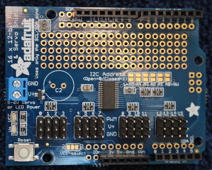
The Adafruit PWM/Servo Shield is a small board which plugs onto an Arduino (an Arduino shield). The shield has 16 pulse width modulators (PWMs) for controlling up to 16 servos. The board comes with 16 servo-compatible headers. The 16 PWMs are numbered from 0-15 (see the Adafruit specification for details). The PWM/Servo Shield uses the Arduino's I2C bus for configuration and control. The bus lets you set the overall PWM frequency for all the PWMs as well as the duty cycle of individual PWMs. Note: if you use this board to control servos, you should know that servos operate over a constrained duty cycle. As a ballpark number, our servos rotated from 0-180 degrees when operated over a ~5-14% duty cycle and a 60Hz frequency. The Servo Shield Device takes non-whole numbers at its terminals, so your duty cycles can be quite precise (e.g. you could move your servo a hair by going from a duty cycle of 6.1 to 6.11). Configuring the ShieldTo configure the Adafruit PWM/Servo Shield, run the PWMServoShield Script in the Adafruit subdirectory. The Script adds 16 input terminals to your Arduino Device, one for each PWM. Each of the inputs takes a duty cycle value from 0-100, or the values "on" or "off" ("on" is the same as a duty cycle value of 100, and "off" is the same as a duty cycle value of 0). The PWMServoShield Device's terminal names are user definable. Note: if you wish to have your servos operate over a 0-180 value range instead of the ~4-15 (duty cycle) range, consider creating a Mapper Device to map degrees to duty cycle. Wire the "out" output of the Mapper to a PWM terminal on your PWMServoShield Device and use the Mapper's "in" input for your 0-180 values. Your Mapper will look something like:
The PWMServoShield Script takes the following parameters:
If you want to leave a terminal off of your Arduino, define its name as the empty string (""). Here's an example using the PWMServoShield Script. It adds a Servo Shield with servos connected to the shield's 2, 3, and 4 servo outputs. It's running at 60Hz and is plugged into an Arduino with ID "arduino". The servo terminals are named "pwm2", "pwm3" and "pwm4".
|
Catalina Computing, LLC.Copyright © Catalina Computing, LLC. (2013-2018) 
|
Page last updated: Tue Oct 7 17:58:21 2014 (UTC) |